Valve for hydraulic control and balancing of fluid flow rate

a hydraulic control and fluid flow rate technology, applied in the field of valves for hydraulic control and fluid flow rate balancing, can solve the problems of further cramped or unavailable rooms, difficulty for operators to have enough rooms, and disadvantages of the mentioned control-balancing valves, etc., to achieve convenient balancing, easy balancing, adjustable and maneuverable

Pending Publication Date: 2022-05-12
GIACOMINI
View PDF67 Cites 1 Cited by
  • Summary
  • Abstract
  • Description
  • Claims
  • Application Information

AI Technical Summary

Benefits of technology

[0025]A further object of the invention consists of providing a valve for hydraulic control and balancing of fluid flow rate which can be easily arranged, adjustable, and maneuverable by an operator in extremely narrow rooms typical of cabinets and manifold general boxes containing a high number of interconnecting pipes or conduits, without using levers, taps, wheels or other handling servomechanisms outside the body of the valve itself.
[0026]A further object of the invention consists of providing a valve for hydraulic control and balancing of fluid flow rate, capable of being easily arranged and adaptably paired with a multiway diverter valve or capable of being associated to already existent plants.

Problems solved by technology

The above-mentioned cited known control-balancing valves, or PICVs, have however disadvantages and operating limitations, particularly when they are used in combined circuits and hydronic plants for heating and cooling, provided with diverter valves.
A serious drawback of these cited types of control / balancing valves, particularly in combined heating-cooling hydronic plants, is due to the size thereof and to the lack of room available for mounting them, and due to the fact that in both the delivery-return connecting manifolds of the user and the diverter valve connecting manifolds, there is a great number of hydraulic connecting conduits and pipes which must be often arranged and placed in small and narrow spaces, such as cassettes or junction boxes.
Particularly, in plants made and configured to already existing buildings and houses, rooms are further cramped or unavailable.
A further typical limit and drawback of conventional combined heating-cooling hydronic plants provided with diverter multi-way valves is due on that nominal flow rates of the fluid thermal carrier required by the user in heating mode are generally different from flow rates in cooling mode, consequently it is required to use flow rate control means or valves configured to change the amount of the fluid thermal carrier flow entering the diverter valve, depending on whether flow comes from a hot or a cold source.
Therefore, it is extremely difficult for an operator to have enough rooms in which easily install said conventional valves for hydraulic control and balancing of the flow rate and for connecting them to conduits and delivery manifolds at the inlet of the diverter valve from different thermal sources.
Moreover, it is also difficult or even impossible to ensure the further handling room or convenience required to actuate the control / balancing valve itself, both if it's of a manual type by means of a lever, knob, wheel or tap, or it's of an automatic type by means of electric or electromechanical actuators or servomechanisms; therefore, even though it were possible to physically install a valve, the required room for manual handling or housing of remotely controlled electromechanical actuators or servomechanisms, will be still cramped or uncomfortable.
Still, a further limit of the conventional control balancing valves, is due to the fact that said handling room or convenience and space for housing an actuator or servomechanism increase proportionally to the fluid passage cross-section of the valve itself.
Moreover, a further drawback of small-sized and geometrically simple dynamic balancing valves which are not provided with membranes or other types of means configured to measure inlet and outlet pressure, is due to the fact that they regulate the fluid flow rate generally only as a function of the inlet momentum applied to regulating members instead of control the flow rate also as a function of the fluid pressure difference between the valve inlet and outlet ports.
A still further limit of the conventional control balancing valves is due to their low ratio of the fluid passage cross-section to the outer size of the valve, and due to the fact that the presence of inner members, their size and sudden changes of direction they impose to the fluid, limits the outlet maximum flow rate so that an user is forced to choose larger valves.
This conventional technical approach, despite being suitable in installation narrow rooms and volumes, has also limits and drawbacks because nor it makes possible further regulating due, for example, to changed conditions of a user plant after modifications or expansion, neither enables an operator to visually check the calibrated diameter of a beforehand installed washer.
Indeed, in up-to-date engineering type implementations, it is sought the capability of a plant to be easily adaptable and modifiable as a function of changed needs of a user, for example caused by future extensions or modifications, which is not possible in the above cited examples except for disconnecting, disassembling or opening the manifolds, connecting conduits between the ports of the diverter valve for replacing or recalibrating of control means, such as calibrated washers, such operation, besides being disadvantageous and uncomfortable, entails costs and the requirement of a skilled technical operator.

Method used


Image

  • Valve for hydraulic control and balancing of fluid flow rate
  • Valve for hydraulic control and balancing of fluid flow rate
  • Valve for hydraulic control and balancing of fluid flow rate

Examples


second embodiment

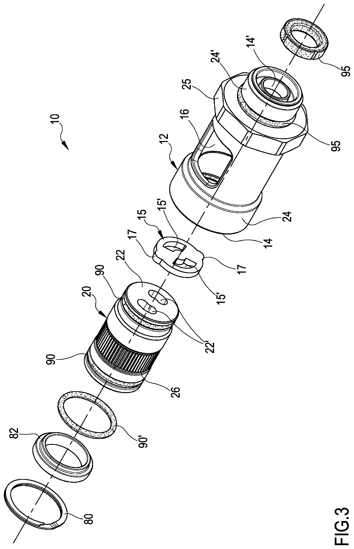
[0045]Moreover, it is made reference to Figures from 4 to 6 and from 11 to 14, which show the valve for hydraulic control and balancing of fluid flow rate object of the present invention, generally indicated by 10′ and both configured to statically control or pre-regulate and dynamically balance a fluid flow rate. Said valves 10, 10′ comprise:

[0046]a body 12 generally having a substantially tubular cylindrical shape provided with an inlet opening 14, outlet opening 14′ disposed at the ends of said body 12 and having at least one actuating opening 16 radially formed on the body 12 itself;

[0047]a hollow rotating shutter 20 rotatively housed inside said body 12, with respect to a rotation axis 11, said rotating shutter 20 being configured to be crossed by a fluid and to rotatively change the passage cross-section of a fluid inside the body 12 itself of the valve 10, 10′.

[0048]Referring in particular to FIGS. 9 and 10 and 13 and 14, the valve 10, 10′ comprises the novel characteristics ...

first embodiment

[0058]Referring to FIGS. 3, 9, and 10, in the first embodiment, the valve 10 comprises a spacer 82 housed in said body 12 having substantially an annular shape, said spacer 82 being configured to close the opening 14 in order to prevent the inner elements to be extracted from the body 12 of the valve 10.

[0059]Valve 10, 10′ can also comprise conventional first fluid sealing elements 90 disposed between the body 12 and rotating shutter 20 and second fluid sealing elements 90′ disposed between said rotating shutter 20 and said spacer 82. Said first and second sealing elements 90, 90′ can be further fit and housed in mated seats or recesses formed on the same rotating shutter 20 and spacer 82 or, alternatively, formed on the body 12 inner surface.

[0060]Valve 10, 10′ can comprise also conventional third fluid sealing elements 95 disposed between the body 12 and other connecting elements, hydraulic devices or valves, not shown, said third fluid sealing elements 95 being generally fit and ...


PUM


Abstract

A valve for hydraulic control of fluid flow rate, comprising: a body provided with an inlet opening, an outlet opening and an actuating opening; a rotating hollow shutter rotatively housed inside said body, said rotating shutter being configured to be crossed by a fluid and to change the passage cross-section inside the valve, in which the rotating shutter comprises at least one first opening rotatively cooperating with at least one mated second eccentric opening, said rotating shutter being configured to be manually actuatable inside the body so that a rotation of said first opening with respect to said second opening is matched by a variation of the fluid passage cross-section in a direction substantially coinciding with the rotation axis.

Description

RELATED APPLICATIONS[0001]This application is a national phase application of and claims priority under 35 U.S.C. § 371 of PCT Patent Application Serial No. PCT / IB2020 / 051434 filed on Feb. 20, 2020 and titled VALVE FOR HYDRAULIC CONTROL AND BALANCING OF FLUID FLOW RATE. The content of this application is incorporated herein by reference.FIELD OF THE INVENTION[0002]The present invention relates to a valve for hydraulic control and balancing of fluid flow rate.[0003]More particularly, the present invention refers to a new technical approach to a valve or hydraulic device for static control and dynamic balancing of the fluid flow rate in a conduit, particularly and in a non-limiting way, to the use in hydronic plants and thermotechnical plants for heating and cooling residential or industrial environments.BACKGROUND OF THE INVENTION[0004]Valves for hydraulic control and balancing of a fluid flow rate, known also as PICVs (Pressure Independent Control Valves) are typically used in hydra...

Claims


Application Information

Patent Timeline
Patent Type & Authority Applications(United States)
IPC IPC(8): F16K15/18F16K15/02G05D7/01
CPCF16K15/182G05D7/014F16K15/028F16K3/085F16K3/32F16K3/265
Inventor MOLINA, SAMUELEZUFFELLATO, ANDREAROSA BRUSIN, MARCOARRUS, PAOLO
Owner GIACOMINI
Why Eureka
Try Eureka