Acceleration transducer

a transducer and acceleration technology, applied in the field of acceleration transducers, can solve the problems of inability to avoid, piezoelectric materials, limited space available for attaching the acceleration transducer to the physical object, etc., and achieve the effect of low weight and low cos

Active Publication Date: 2022-05-05
KISTLER HLDG AG
View PDF15 Cites 4 Cited by
  • Summary
  • Abstract
  • Description
  • Claims
  • Application Information

AI Technical Summary

Benefits of technology

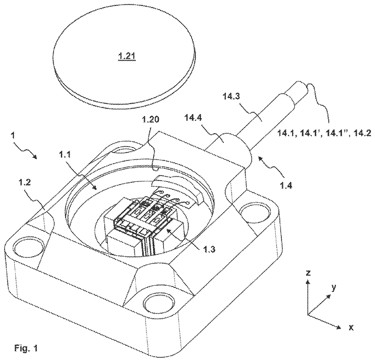
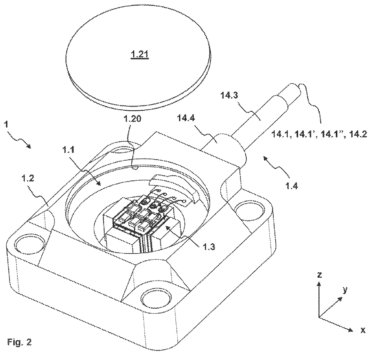
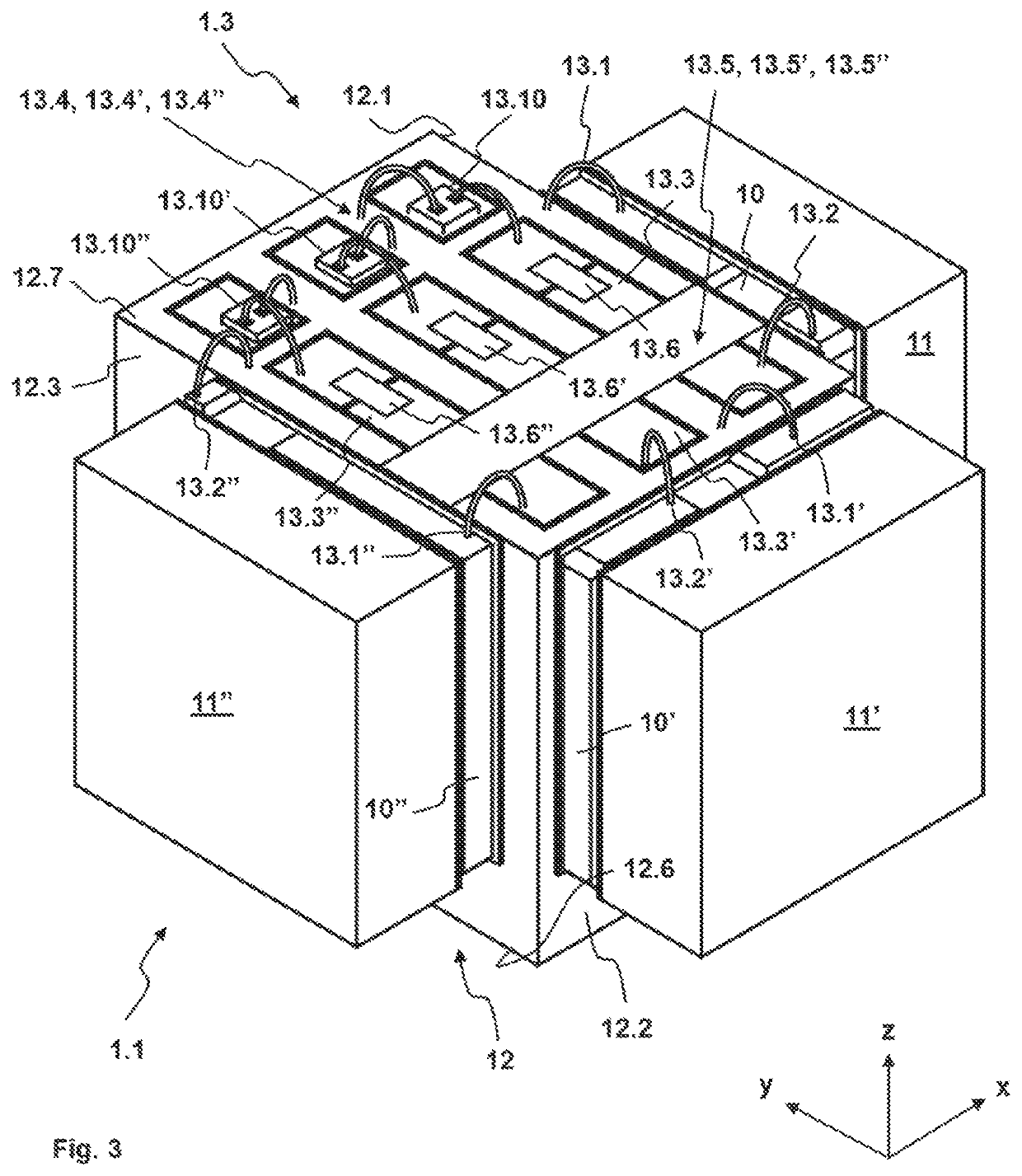
The present invention provides an acceleration transducer that can detect acceleration in multiple dimensions simultaneously, with minimal falsification. The transducer is small in size, low in weight, and can operate at high frequencies of over 10 kHz. The invention also includes a direct or indirect arrangement of the converter unit on the main body, which allows for quality control and cost-effective assembly. Additionally, the invention ensures no force shunt occurs between the seismic mass and the main body, and provides easy access for contacting the piezoelectric element and converter unit for easy and quick testing and installation.

Problems solved by technology

Unfortunately, it cannot be avoided that piezoelectric material has more or less high sensitivities for shear forces acting along different axes.
There is often limited space available for attaching the acceleration transducer to the physical object.
However, this arrangement of the converter unit on lateral surfaces of the pre-loading sleeve and seismic mass as well as on the normal end face of the main body presents a disadvantage of the introduction of a force shunt that forms between the seismic mass and the main body.
As a result, the seismic mass no longer can oscillate freely under the effect of an acceleration, and a force acting onto the piezoelectric system due to the inertia of the seismic mass is impeded so that the force is no longer proportional to the acceleration.
In addition, the piezoelectric charges generated by the piezoelectric material are no longer proportional to the acceleration to be detected.

Method used


Image

  • Acceleration transducer
  • Acceleration transducer
  • Acceleration transducer

Examples


first embodiment

[0068]Referring to FIGS. 7 and 8, according to a first, second or third piezoelectric element 10, 10′, 10″ the first end face 110 schematically shown in FIG. 7 comprises two first electrically conductive end face coatings 111, 111′ in some areas thereof and two first uncoated end face areas 112, 112′ in some areas thereof. Furthermore, the second end face 120 schematically shown in FIG. 8 comprises two more electrically conductive end face coatings 121, 121′, 121″ in some areas thereof. The first lateral surface 130 comprises a first electrically conductive lateral surface coating 131 in some areas thereof, another first electrically conductive lateral surface coating 133 in some areas thereof, and a plurality of uncoated first lateral surface areas 132, 132′, 132″, 132′″, 132″″ in some areas thereof. The second lateral surface 140 schematically shown in FIG. 8 comprises a second electrically conductive lateral surface coating 141 in some areas thereof and a second uncoated lateral ...

second embodiment

[0073]According to a first, second, or third piezoelectric element 10, 10′, 10″ as shown in FIGS. 9 and 10, the first end face 110 comprises a first electrically conductive end face coating 111 in some areas thereof and a plurality of first uncoated end face areas 112, 112′, 112″ in some areas thereof. Furthermore, the second end face 120 schematically shown in FIG. 10 comprises a plurality of second electrically conductive end face coatings 121, 121″, 121″ in some areas thereof and a second uncoated end face area 122 in some areas thereof. The first lateral surface 130 comprises a first electrically conductive lateral surface coating 131 in some areas thereof, two additional first electrically conductive lateral surface coatings 133, 133′ in some areas thereof, and a plurality of uncoated first lateral surface areas 132, 132′, 132″ in some areas thereof. The second lateral surface 140 comprises a second electrically conductive lateral surface coating 141 in some areas thereof and a...


PUM


Abstract

An acceleration transducer defines a rectangular coordinate system with two orthogonal horizontal axes that are both normal to a vertical axis and includes a main body defining tangential side faces arranged tangentially to the vertical axis, and normal side faces arranged normally to the vertical axis. The transducer includes a converter unit, exactly three piezoelectric elements and three seismic masses. Each piezoelectric element generates piezoelectric charges transmitted to the converter unit, which is only and directly arranged on a normal side face of the main body or only on a support that is attached to a normal side face of the main body. Exactly one piezoelectric element is secured to each of the three tangential side faces, and exactly one seismic mass is secured to each of the three piezoelectric elements. Each piezoelectric element has a high sensitivity for a shear force exerted by the attached seismic mass along a principal tangential axis that is another one of the three axes for each of the three piezoelectric elements.

Description

FIELD OF THE INVENTION[0001]The present invention relates to an acceleration transducer that can be attached to an object and in which movement of a seismic mass against a piezoelectric element lodged against a rigid main body generates electric charges that are collected and processed to yield measurements of forces indicative of acceleration of the object.BACKGROUND OF THE INVENTION[0002]Accelerations of a physical object are measured in numerous widely varied applications such as robotics, energy generation, transportation, and so on. For this purpose, accelerations are detected in the form of shocks that act onto the physical object and of vibrations of the physical object. Accelerations are indicated as multiples of the gravitational acceleration g=9.81 msec−2. Typical ranges of detected accelerations are + / −500 g in measuring ranges from 2 Hz to 10 kHz. An acceleration transducer is secured to the physical object for detecting accelerations.[0003]The document CH399021A1, which...

Claims


Application Information

Patent Timeline
Patent Type & Authority Applications(United States)
IPC IPC(8): G01P15/09G01P15/18G01P1/02
CPCG01P15/0915G01P1/023G01P15/18G01P15/09G01P15/0802G01P15/097
Inventor LAFFRANCHI, MARCOFROMMENWILER, TOBIASWEBER, DAVID
Owner KISTLER HLDG AG
Why Eureka
Try Eureka