Microscope for quantitative wavefront measurements, microscope module and kit, method and computer program for computational wavefront reconstruction

a microscope and wavefront technology, applied in the field of microscopes for quantitative wavefront measurements, can solve the problems of limited resolution, low stability of monocular information, and process, and achieve the effect of improving the spatial resolution

Pending Publication Date: 2022-04-28
UNIV DE VALENCIA
View PDF0 Cites 1 Cited by
  • Summary
  • Abstract
  • Description
  • Claims
  • Application Information

AI Technical Summary

Benefits of technology

The microscope proposed in this patent is a compact and easy-to-use tool for measuring the wavefront in microscopic samples. It has a unique design that allows for accurate wavefront measurements in three dimensions. The microscope is easy to install and requires minimal alterations to existing microscopes. It utilizes a special lens array with a large spacing and small relative aperture, resulting in improved spatial resolution compared to conventional microscopes. The microscope is stable and simple to use, making it a useful tool for research and industry. Overall, this patent describes a compact, affordable, and highly efficient solution for measuring wavefront in microscopic samples.

Problems solved by technology

1) Microscopes based on the interferential detection of the wavefront by means of a holographic process. This type of systems presents the disadvantage of its low stability and that of obtaining only monocular information.
Although each of the proposals made in said patents achieves a certain improvement in the spatial resolution of the microscopes proposed therein, said improvement clearly leaves room for further improvement, as the improvement in spatial resolution achieved has the limitations of the systems based on Hartmann-Shack sensors, the resolution whereof is limited by the number of microlenses (independently of the spatial resolution of the pixelated sensor).
However, there are two main limitations to said process:
Furthermore, said size limits the number of pixels in which the wavefront is sampled for a particular size of sensor.
This is why H-S sensors are normally used to measure slight variations in the wavefront, and their use in the measurement of the light scattered in biological samples is certainly limited.
On the other hand, the mechanisms proposed in the aforementioned patents based on the Hartmann-Shack principle present a certain complexity; it would therefore also be convenient to propose simpler alternative mechanisms.

Method used


Image

  • Microscope for quantitative wavefront measurements, microscope module and kit, method and computer program for computational wavefront reconstruction
  • Microscope for quantitative wavefront measurements, microscope module and kit, method and computer program for computational wavefront reconstruction
  • Microscope for quantitative wavefront measurements, microscope module and kit, method and computer program for computational wavefront reconstruction

Examples


Embodiment Construction

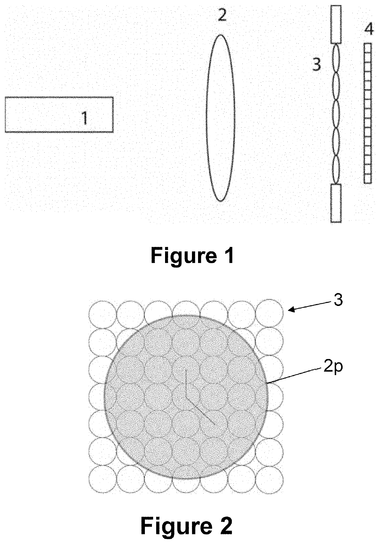
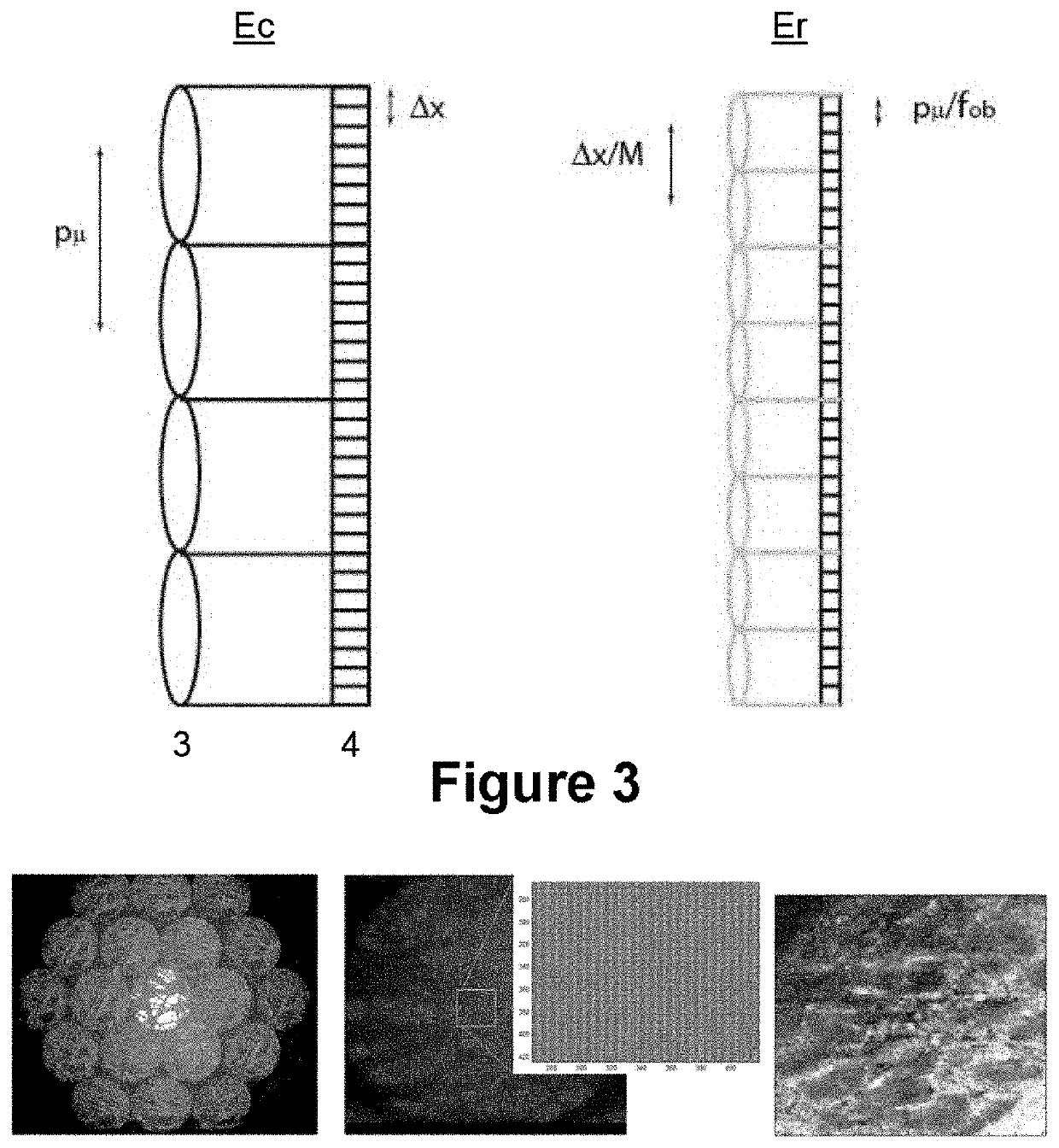
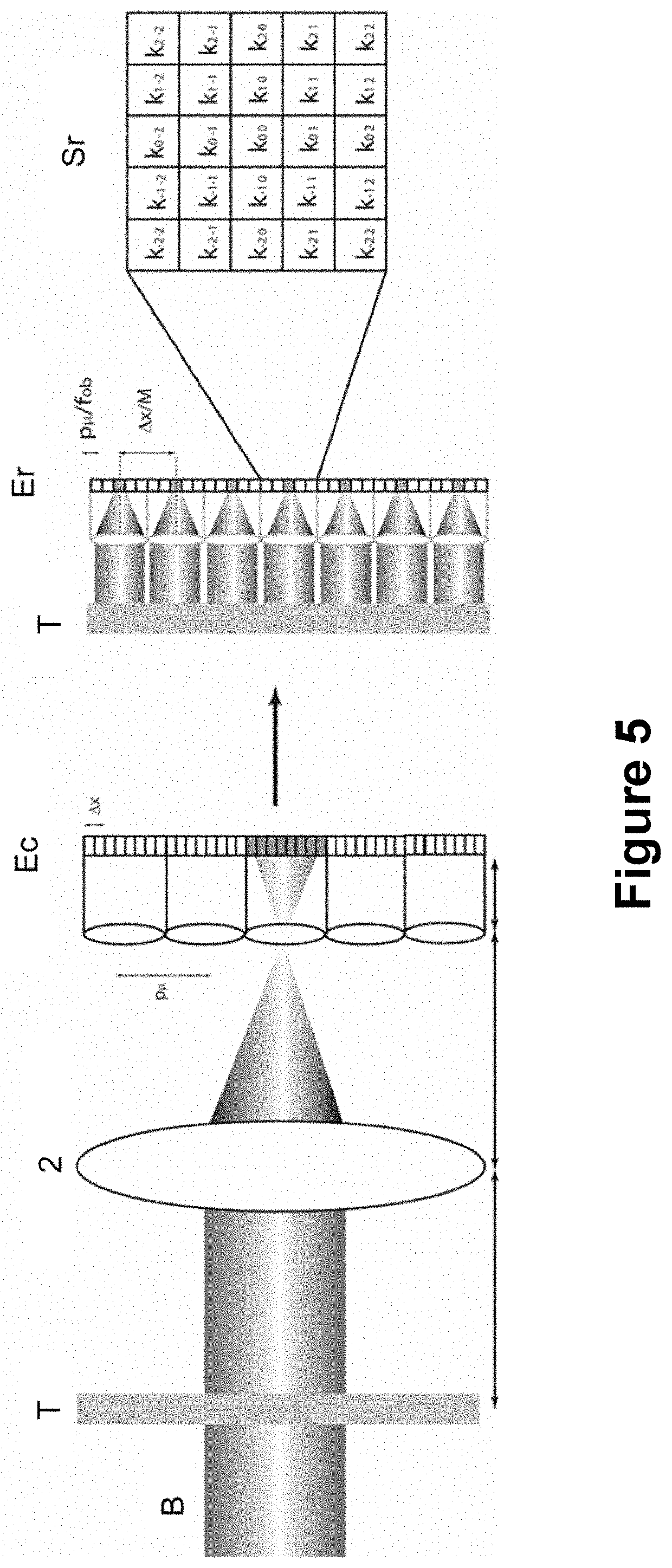
[0069]As illustrated schematically in FIG. 1, for its most basic embodiment the microscope proposed by the first aspect of the present invention comprises:[0070]illumination means comprising a partially or totally coherent light source 1, to illuminate a sample T (illustrated schematically in FIG. 5);[0071]a microscope objective lens 2 configured and arranged to receive and focus the light scattered by the sample T when illuminated by said illumination means 1;[0072]an ordered two-dimensional arrangement of lenses 3 located at the aperture diaphragm of said microscope objective lens 2 or at the location of an intermediate image thereof;[0073]an image sensor 4, or pixelated sensor, formed by a plurality of photodetector elements or pixels, located at a capture space on the focal plane of the ordered two-dimensional arrangement of lenses or lens matrix 3, to receive the light scattered by the sample T subsequent to crossing the microscope objective lens 2 and the ordered two-dimension...


PUM


Abstract

The present invention relates to a microscope for quantitative measurements of the wavefront, comprising:means for the illumination of a sample (T);an objective lens (2);an ordered two-dimensional arrangement of lenses (3), with a spacing pμ greater than 500 μm and a relative aperture of less than 10;an image sensor (4) located in a capture space (Ec) to receive the light scattered by the sample (T), and to acquire spatial and angular information on the object wavefront associated therewith; anda computational entity to perform a computational reconstruction of the object wavefront from the spatial and angular information.Other aspects of the invention relate to a method, a computer program and a product incorporating the same, adapted for the performance of the functions of the computational entity of the microscope, as well as to a module and a kit for a microscope.

Description

FIELD OF THE INVENTION[0001]The present invention relates, in a first aspect, to a microscope for quantitative measurements of the wavefront, comprising an ordered two-dimensional arrangement of lenses designed in such a way that it enables the measurement of slight and non-slight variations in the wavefront from biological samples, or the obtaining of high-resolution 3D images, including those from microscopic samples.[0002]A second aspect of the present invention relates to a method for the computational reconstruction of the wavefront, adapted to perform the functions for which the computational entity of the microscope is configured.[0003]In a third aspect, the present invention relates to a computer program for the computational reconstruction of the wavefront, including program instructions which, when executed in a processor, implement the method of the second aspect.[0004]In a fourth aspect, the present invention relates to a computer program product comprising a tangible me...

Claims


Application Information

Patent Timeline
IPC IPC(8): G01J9/00G02B21/06G02B21/36
CPCG01J9/00G02B21/365G02B21/06G02B3/0056G02B21/086G02B21/361G02B30/10G02B21/36
Inventor MARTÍNEZ CORRAL, MANUELSAAVEDRA TORTOSA, GENAROSÁNCHEZ ORTIGA, EMILIOTÖRÖK, PETER
Owner UNIV DE VALENCIA
Why Eureka
Try Eureka