
Intravenous fluid bag supporting assembly

a technology of fluid bag and supporting assembly, which is applied in the direction of intravenous devices, medical devices, medical devices, etc., can solve the problems of waste of resources, waste of resources, waste of resources, etc., and achieves the effects of reducing the likelihood, improving the ease of use, and improving sanitation and environmental concerns

Pending Publication Date: 2022-04-21
SMITH WALTER L
View PDF32 Cites 0 Cited by
  • Summary
  • Abstract
  • Description
  • Claims
  • Application Information

AI Technical Summary

Benefits of technology

The invention is a mobile IV pole assembly that improves efficiency and patient comfort. It is designed with all the components arranged in a compact way, making it easier for medical professionals to connect the different parts. The arrangement of the IV fluid lines within the support platform reduces the risk of misidentification or tangling. The axial arrangement also improves waste management, sanitation, and environmental concerns. The uniform distance between the top of the structure and the support platform's underside allows for the use of shorter IV fluid lines, which are housed in the support platform's housings. This design reduces plastic waste. Overall, the invention improves the overall experience of IV therapy.

Problems solved by technology

IV poles are designed to assist in uniform dosing of fluids at uniform rates but can be confusing for care givers and cumbersome for patients.
For care givers, problems stem from potentially having four pumps attached to a single display, coupled with IV fluid bags hanging above the displays and pumps and arranged in no particular order.
Care giver efficiency is lost when trying to ensure that the correct fluid lines are connected at the access points.
Furthermore, a single, central display with pumps on each side can be confusing to read, leading to dosing and dispensing errors.
The number and arrangement of these devices can further contribute to delays in rapid identification, label reading errors and misidentification of IV fluid bags and corresponding medical devices.
For many patients, the IV pole is a necessary evil.
Unfortunately, prior art IV poles are not friendly in this regard.
Pumps are attached to the sides of the displays, and the displays are then attached to the pole, making the pole assembly unbalanced.
The mobility of patients is further inhibited when medical lines become caught in the IV pole wheels or become tangled and drag on the floor.
Patients walking with such poles find them awkward and unwieldy.
Patient injury can also result from accidentally kicking or tripping over exposed wheels and spokes while walking along side such IV stand base configurations.
Additional drawbacks of these arrangements can be found in the directional orientation of the hooks.
Health care providers may have difficulty mounting the bags on the hooks.
Once hung, owing to the height of the hooks and bag arrangement, care givers have difficulty viewing the fluid bags and labels to identify the contents, particularly for patients requiring large numbers of contemporaneous transfusions.
This can be difficult if the bags and associated fluid lines are attached to a patient.
Furthermore, such arrangements may contribute to delays in rapid label identification, leading to label reading errors and misidentification of IV fluid bags.
In addition, multiple lengths of flexible tubing extend from the IV fluid bags to the patient and may become crossed or entangled with one another, increasing the burden on medical personnel to distinguish one length of tubing from another when connecting the tubing to the fluid bags and to the patient and / or when injecting additional medications into the patient via tubing inlets.
Because such arrangements lack uniformity in the distance spanned from any one hook to any one pump, IV fluid lines are excessively long.
Unnecessarily long IV fluid lines may become entangled in IV pole wheels, requiring a patient to push, lift or otherwise manipulate the IV stand to free the entangle line.
Such actions lead to additional confusion as to the origin and destination of IV fluid lines.
Mobile IV stands may not have a handle for a patient to comfortably grasp while walking.
Where handles are provided, they are not easily adjusted to a height comfortable for each individual user or may include a mounting configuration that is not easy for a patient to safely and comfortably grasp for stability while walking.
Some handles place an undue strain on a user's hand and wrist resulting in discomfort and fatigue.
This results in a conglomeration of medical devices, a plurality of power cords and electronic wiring that leads to a tangled mass of cords and wires spread on a hospital room floor providing a source of contamination and infection spread.
This is awkward and inefficient on the one hand.

Method used


Image

  • Intravenous fluid bag supporting assembly
  • Intravenous fluid bag supporting assembly
  • Intravenous fluid bag supporting assembly

Examples


Embodiment Construction

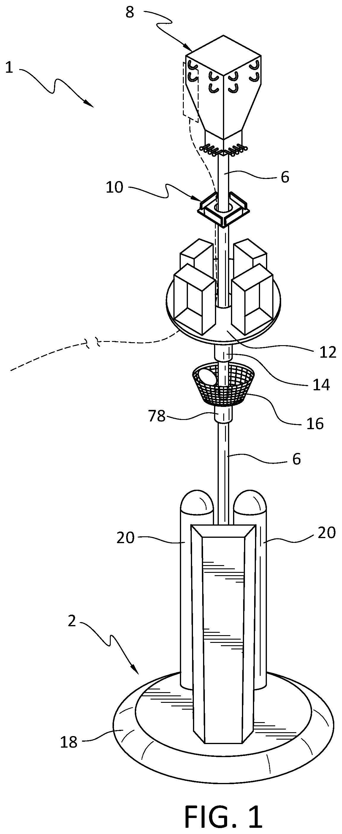
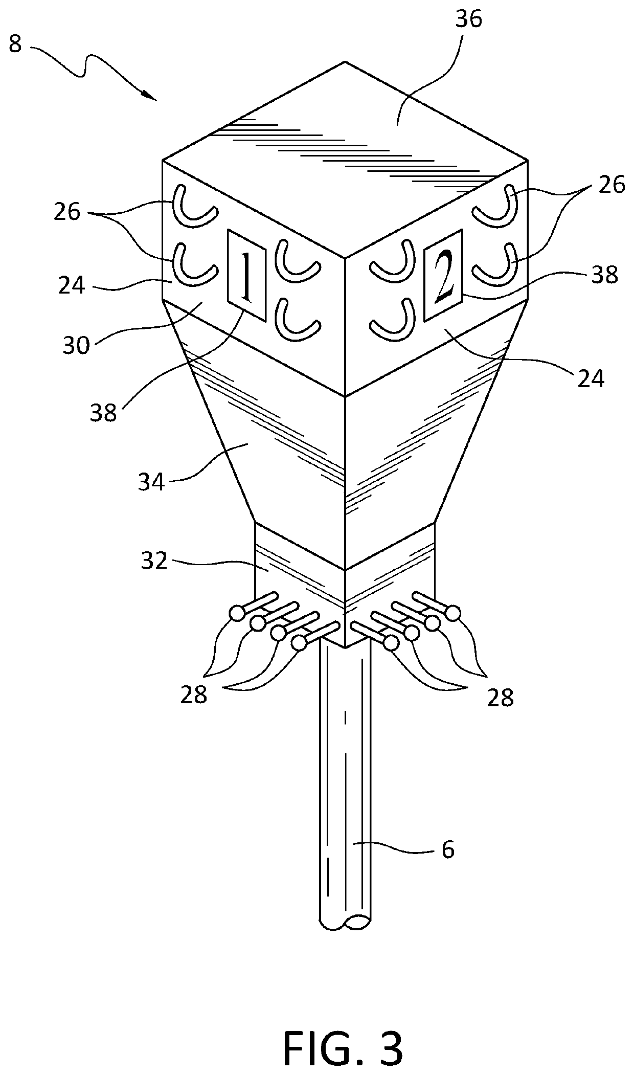
[0040]The IV fluid bag supporting assembly 1 of FIG. 1 includes a mobile base 2 having a plurality of wheels 4, a telescoping pole 6 having a lower end connected with the mobile base 2, and an inverted polyhedron structure 8 connected with an upper end of the pole 6. The inverted polyhedron structure 8 is configured to receive at least one IV fluid bag. The IV fluid bag support assembly 1 also includes a light assembly 10, a support platform 12, a hand grip or handle 14 and a basket 16.

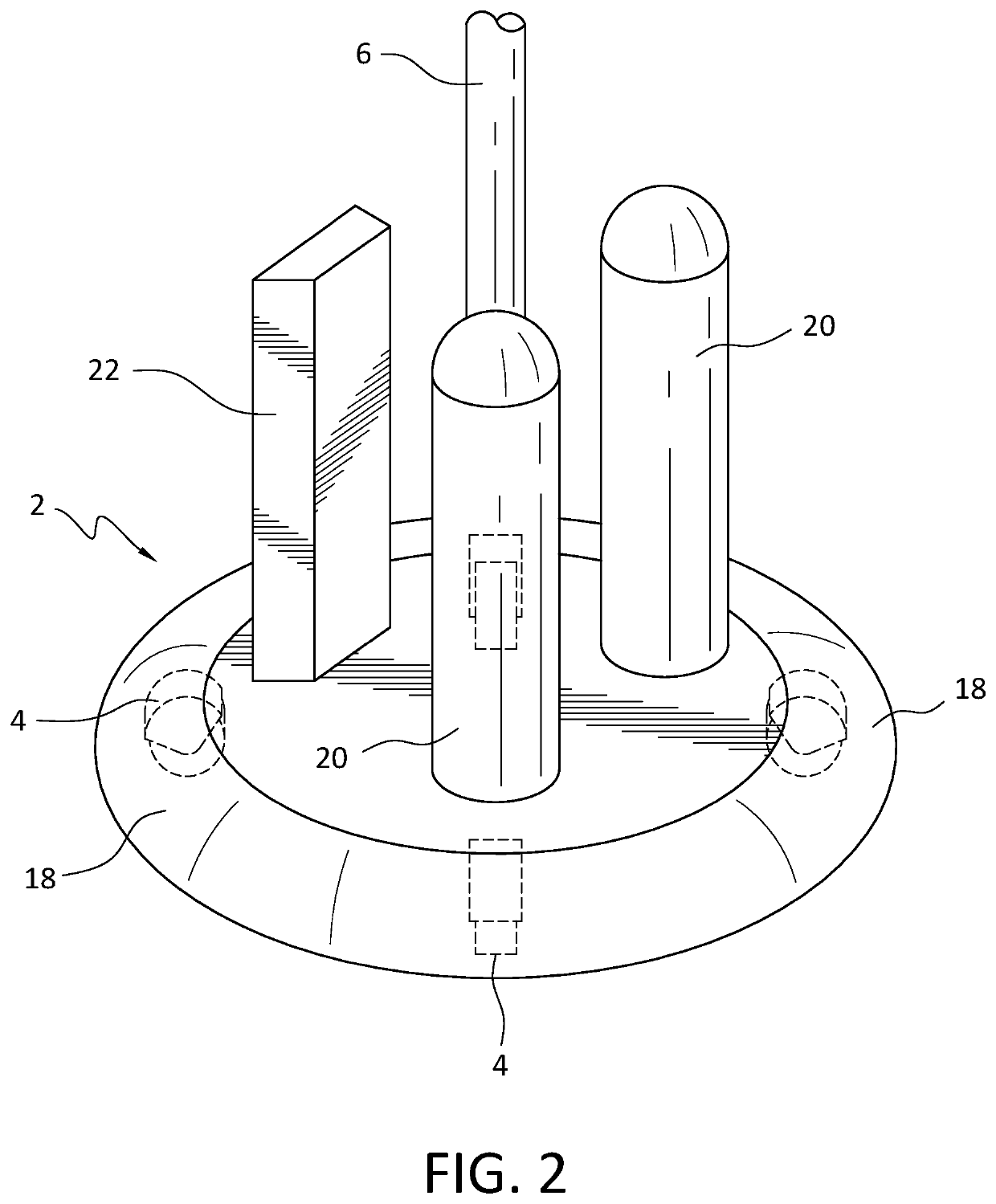
[0041]As illustrated in FIG. 2, the wheels 4 of the mobile base 2 may be casters, encased ball bearing wheels or any other suitable wheel assembly. The mobile base 2 may be encircled by a wheel cover or skirt 18 as shown in FIG. 1. In an example, the wheel cover 18 may be fixed, hinged, removable or connected with the base by any other suitable arrangement.

[0042]The mobile base 2 may be sized and configured to receive at least one of an oxygen tank 20, a power outlet strip or bar 22 and other equipmen...


PUM


Abstract

An intravenous fluid bag supporting assembly includes a mobile base having a plurality of wheels, a telescoping pole having a lower end connected with the base and an inverted polyhedron structure connected with an upper end of the pole and configured to receive at least one intravenous fluid bag. An adjustable light assembly is arranged on the pole in spaced relation between the inverted polyhedron structure and the base. A support platform is arranged on the pole in spaced relation between the light assembly and the base, the support platform supporting a plurality of housings configured to receive a plurality of displays and pumps or other medical instruments, respectively. A hang grip and basket are also arranged on the pole.

Description

BACKGROUND OF THE DISCLOSURE[0001]A conventional intravenous (“IV”) fluid bag stand or pole has two components: a wheeled base for multidirectional movement and a hook assembly or attachment for receiving one or more intravenous fluid bags.[0002]IV poles are designed to assist in uniform dosing of fluids at uniform rates but can be confusing for care givers and cumbersome for patients. For care givers, problems stem from potentially having four pumps attached to a single display, coupled with IV fluid bags hanging above the displays and pumps and arranged in no particular order. To add to the confusion, specific fluid lines must connect with specific access points in a patient. Care giver efficiency is lost when trying to ensure that the correct fluid lines are connected at the access points. To aid in this process, care givers often attach pieces of tape at the top and bottom of IV lines to identify which line is which. Furthermore, a single, central display with pumps on each side...

Claims


Application Information

Patent Timeline
IPC IPC(8): A61M5/14
CPCA61M5/1417A61M5/1415A61M2205/587A61M2209/082A61M2209/084A61M5/1418
Inventor SMITH, WALTER L.
Owner SMITH WALTER L
Learn More