Control device for vehicle

a control device and vehicle technology, applied in the direction of propulsion parts, electric propulsion mounting, transportation and packaging, etc., can solve the problems of inability to obtain engine power, inability to achieve safe gear stages in automatic transmissions, and driver's discomfort, so as to reduce power performance, facilitate limp-home travel, and curb driver's discomfor

Pending Publication Date: 2022-04-14
TOYOTA JIDOSHA KK
View PDF0 Cites 3 Cited by
  • Summary
  • Abstract
  • Description
  • Claims
  • Application Information

AI Technical Summary

Benefits of technology

The patent describes a control device for a vehicle that can improve its performance and comfort during certain driving situations. Specifically, the device can switch between two modes based on the vehicle's speed and the status of the power transmission path. When the vehicle is traveling at a high speed, the device will switch to a mode that uses the power of the engine and the first electric motor to maintain power performance. When the vehicle is stopped or traveling at a lower speed, the device will switch to a mode that uses the second electric motor for limp-home travel, which will improve starting performance and reduce discomfort for the driver. The device also prevents the engine from being used for power transmission when it is not needed, which improves fuel efficiency. Overall, the device helps to maintain the vehicle's performance and comfort during various driving situations.

Problems solved by technology

When an abnormality in the automatic transmission has been detected, a fail-safe gear stage may be formed in the automatic transmission.
However, when an abnormality in the automatic transmission has been detected and the travel mode is evenly switched to a travel mode in which only power of the second electric motor is transmitted to the driving wheels as in the technique described in JP 2006-34054 A, an opportunity to perform limp-home travel using the power of the engine cannot be obtained and there is a likelihood that a driver will feel uncomfortable due to a decrease in power performance.

Method used


Image

  • Control device for vehicle
  • Control device for vehicle
  • Control device for vehicle

Examples


first embodiment

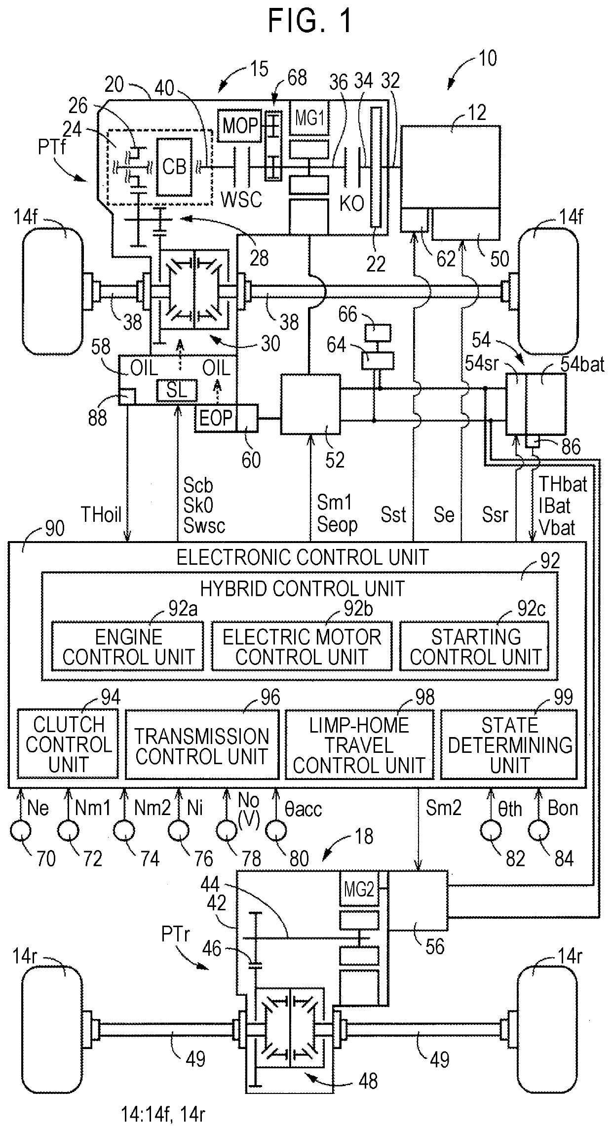
[0031]FIG. 1 is a diagram schematically illustrating a configuration of a vehicle 10 to which the disclosure is applied and illustrating principal parts of a control function and a control system for various types of control in the vehicle 10. In FIG. 1, the vehicle 10 is a hybrid vehicle including an engine 12, a first electric motor MG1, a second electric motor MG2, and driving wheels 14. The engine 12, the first electric motor MG1, and the second electric motor MG2 are driving force sources for travel. The driving wheels 14 include front wheels 14f and rear wheels 14r. The vehicle 10 includes a front power transmission device 16 that is provided in a power transmission path between the engine 12 and the front wheels 14f and a rear power transmission device 18 that is provided in a power transmission path between the second electric motor MG2 and the rear wheels 14r. The first electric motor MG1 is connected to the power transmission path between the engine 12 and the front wheels...

second embodiment

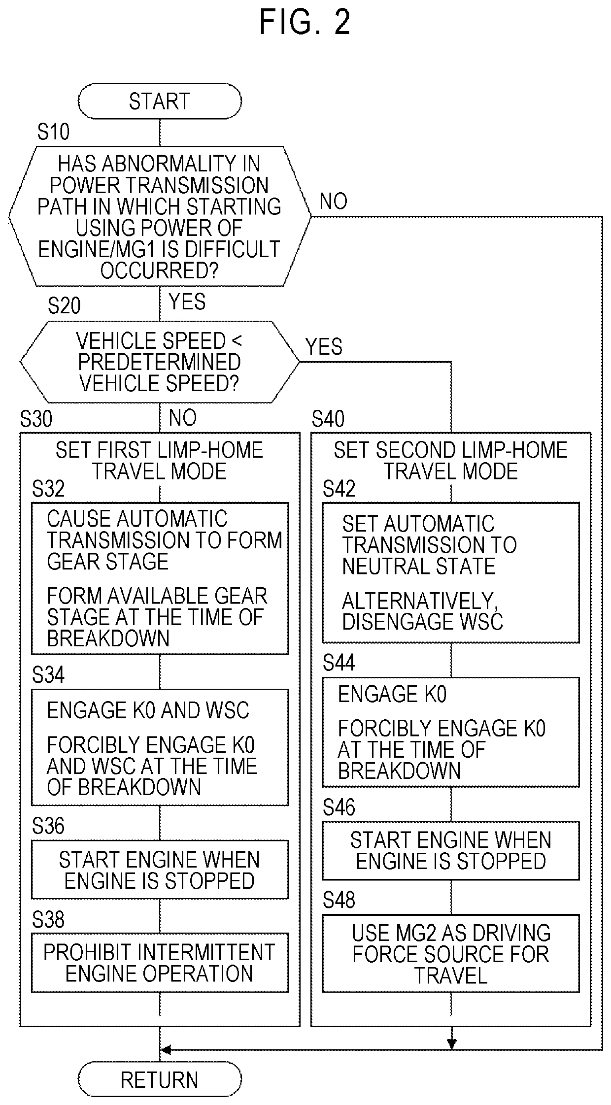
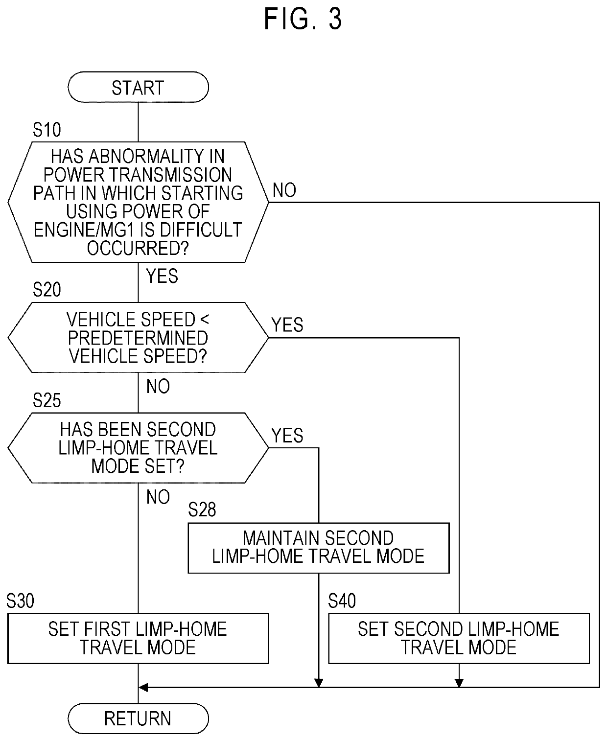
[0111]In the first embodiment, when an abnormality associated with transmission of power in the front power transmission path PTf has occurred, the first limp-home travel mode Mlh1 is set when the vehicle speed V is equal to or higher than the predetermined vehicle speed Vf, and the second limp-home travel mode Mlh2 is set when the vehicle speed V is lower than the predetermined vehicle speed Vf. Switching between the first limp-home travel mode Mlh1 and the second limp-home travel mode Mlh2 depending on the vehicle speed V makes vehicle control complicated. On the other hand, in the second limp-home travel mode Mlh2, it is possible to secure traveling performance and to secure starting performance. In other words, in a normal state in which the limp-home travel mode Mlh is not set, a driver is likely to feel uncomfortable due to a decrease in power performance when an abnormality associated with transmission of power in the front power transmission path PTf has occurred while the v...


PUM


Abstract

When an abnormality associated with power transmission in a power transmission path which is formed such that power of an engine or the like is able to be transmitted to driving wheels has occurred and a vehicle speed is equal to or higher than a predetermined vehicle speed, a limp-home travel control unit switches a limp-home travel mode to a first limp-home travel mode in which the power of the engine or the like is able to be transmitted to the driving wheels through the power transmission path. When an abnormality associated with power transmission in the power transmission path has occurred and the vehicle speed is lower than the predetermined vehicle speed, the limp-home travel control unit switches the limp-home travel mode to a second limp-home travel mode in which limp-home travel is performed using power of a second electric motor.

Description

CROSS-REFERENCE TO RELATED APPLICATION[0001]This application claims priority to Japanese Patent Application No. 2020-171557 filed on Oct. 9, 2020, incorporated herein by reference in its entirety.BACKGROUND1. Technical Field[0002]The disclosure relates to a control device for a vehicle that includes an engine, a first electric motor, a second electric motor, and an automatic transmission.2. Description of Related Art[0003]A control device for a vehicle including an engine, a first electric motor that is connected to the engine in a power-transmittable manner, an automatic transmission that constitutes a part of a power transmission path which is formed to transmit power of the engine and power of the first electric motor to driving wheels, and a second electric motor that transmits power to the driving wheels without passing through the automatic transmission is well known. An example of a drive device for such a hybrid vehicle is described in Japanese Unexamined Patent Application ...

Claims


Application Information

Patent Timeline
Patent Type & Authority Applications(United States)
IPC IPC(8): B60W20/50B60K6/52B60K6/26B60W50/038B60W50/029B60K6/387B60W10/06B60W10/08B60W10/02B60W20/40
CPCB60W20/50B60Y2300/182B60K6/26B60W50/038B60W50/029B60K6/387B60W10/06B60W10/08B60W10/02B60W20/40B60W2050/0292B60W2510/1005B60W2710/06B60W2710/08B60W2710/021B60Y2200/92B60K6/52B60K1/00B60K2001/001B60W10/10B60W10/11B60W2520/10Y02T10/62Y02T10/72B60W2050/0297B60K6/448B60K6/547B60K2006/4825
Inventor NISHIMURA, YUKIMASANISHIU, MASAHIRO
Owner TOYOTA JIDOSHA KK
Why Eureka
Try Eureka