
Continuously variable transmission

a transmission and continuous technology, applied in the direction of belts/chains/gearings, toothed gearings, belts/chains/gearings, etc., can solve the problems of continuous variable output torque will be even more insufficien

Pending Publication Date: 2022-04-07
WEIHAI TUANZHONG TRANSMISSION CO LTD
View PDF6 Cites 5 Cited by
  • Summary
  • Abstract
  • Description
  • Claims
  • Application Information

AI Technical Summary

Benefits of technology

The present invention is a solution for a continuously variable transmission (CVT) that can provide sufficient torque to different driving conditions. The invention has multiple functions and is controlled through an outer housing, four control ends, and three shafts (a first, second, and third shaft). This allows for better performance and efficiency of theCVT.

Problems solved by technology

The disadvantage of this continuously variable transmission structure is as follows.
Since the bucket wheel sun gear and the first sun gear are rigidly connected to the first shaft, when the first shaft of the continuously variable transmission is used as an input end, a torque that provides rotation of the bucket wheel comes from the first shaft, the rotation of the bucket wheel distributes a part of the input torque of the first shaft, and under the working condition that the torque provided by the first shaft is insufficient, the output torque will be even more insufficient; when the second shaft of the continuously variable transmission is used as the input end, a torque that provides rotation of the bucket wheel comes from the first shaft, the rotation of the bucket wheel increases the resistance torque of the first shaft, and under the working condition that the torque provided by the second shaft is insufficient, the output torque will be even more insufficient.
The continuously variable transmission cannot realize increased functions and satisfy more working conditions.

Method used


Image

  • Continuously variable transmission
  • Continuously variable transmission
  • Continuously variable transmission

Examples


embodiment 1

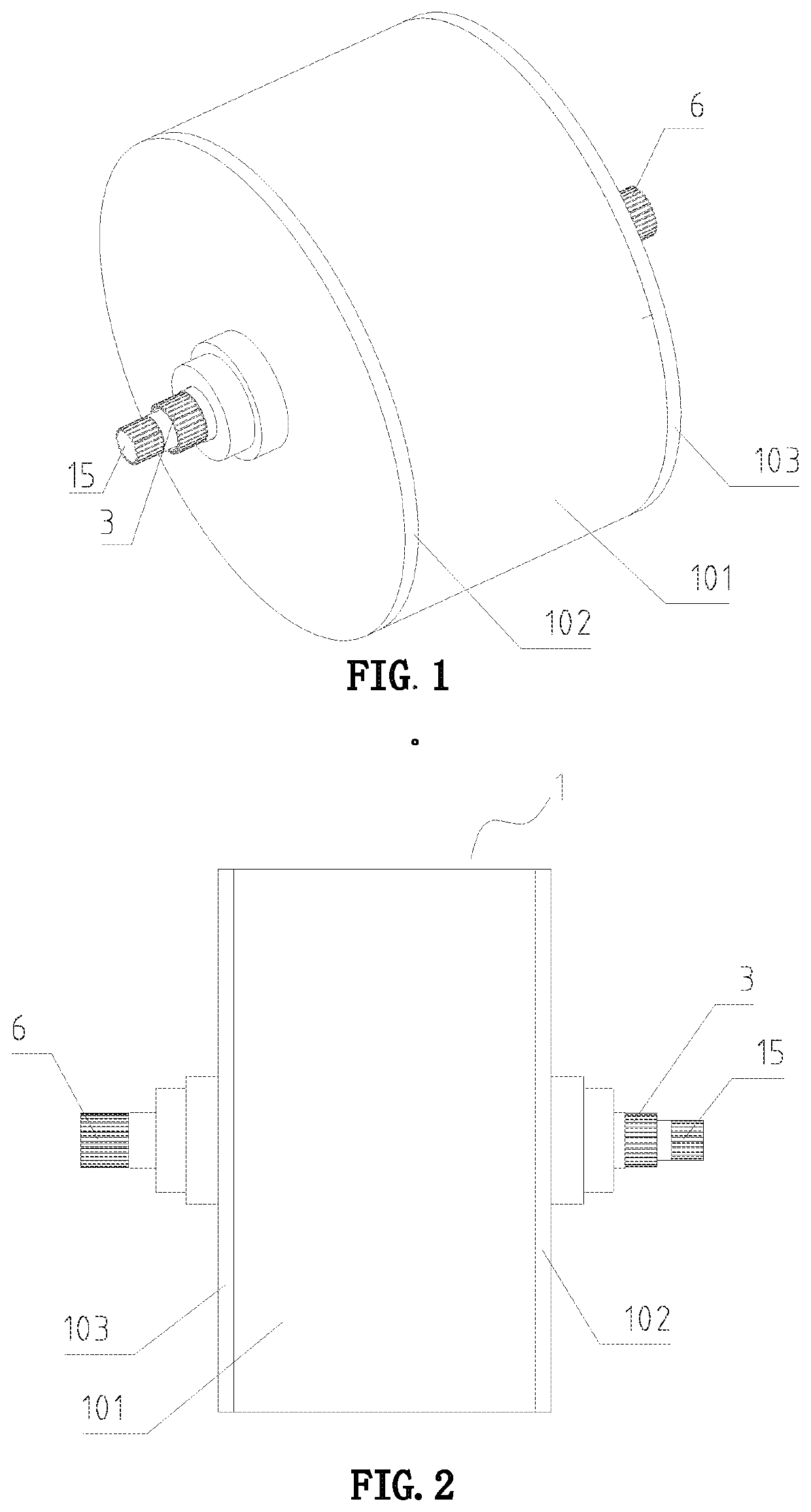
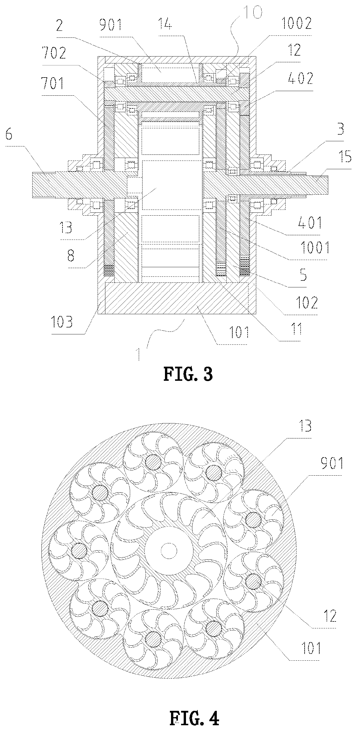
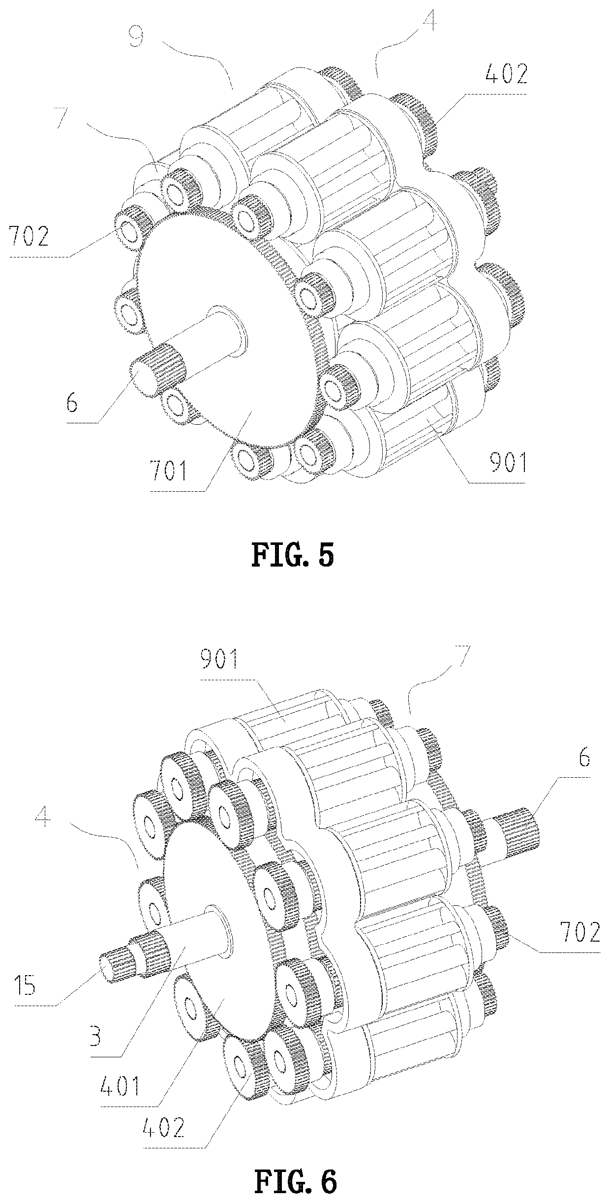
[0029]FIGS. 1-6 show an embodiment of a continuously variable transmission of the present invention. The continuously variable transmission is provided with an outer housing 1, an intermediate housing 101 is provided in the middle of the outer housing 1, a first end cover 102 and a second end cover 103 are respectively provided on both sides of the intermediate housing 101, the inside of the intermediate housing 101 is a cavity structure, and the cavity inside the intermediate housing 101 and insides of the first end cover 102 and the second end cover 103 form an inner cavity 2;

[0030]a first shaft 3 penetrates in the middle of the first end cover 102, the inside of the first shaft 3 is a hollow structure, the first shaft 3 is rotatably connected to the first end cover 102, a first sun gear 401 is fixedly provided on the first shaft 3, the first sun gear 401 is located inside the first end cover 102, the first sun gear 401 is adjacently provided with a first support frame 5, a first ...

embodiment 2

[0041]FIGS. 7-12 show Embodiment 2 of a continuously variable transmission of the present invention. The continuously variable transmission is provided with an outer housing 1, an intermediate housing 101 is provided in the middle of the outer housing 1, a first end cover 102 and a second end cover 103 are respectively provided on both sides of the intermediate housing 101, the inside of the intermediate housing 101 is a cavity structure, and the cavity inside the intermediate housing 101 and insides of the first end cover 102 and the second end cover 103 form an inner cavity 2; a first shaft 3 penetrates in the middle of the first end cover 102, the inside of the first shaft 3 is a hollow structure, the first shaft 3 is rotatably connected to the first end cover 102, a first gear ring 401A is fixedly provided on the first shaft 3, the first gear ring 401A is located inside the first end cover 102, the first gear ring 401A is adjacently provided with a first support frame 5, a first...

embodiment 3

[0044]With reference to FIGS. 3, 6, 9 and 12, Embodiment 3 of the present invention can be formed. A continuously variable transmission is provided with an outer housing 1, an intermediate housing 101 is provided in the middle of the outer housing 1, a first end cover 102 and a second end cover 103 are respectively provided on both sides of the intermediate housing 101, the inside of the intermediate housing 101 is a cavity structure, and the cavity inside the intermediate housing 101 and insides of the first end cover 102 and the second end cover 103 form an inner cavity 2; a first shaft 3 penetrates in the middle of the first end cover 102, the inside of the first shaft 3 is a hollow structure, the first shaft 3 is rotatably connected to the first end cover 102, a first sun gear 401 is fixedly provided on the first shaft 3, the first sun gear 401 is located inside the first end cover 102, the first sun gear 401 is adjacently provided with a first support frame 5, a first planet ge...


PUM


Abstract

A continuously variable transmission, provided with an outer housing (1), wherein an intermediate housing (101) is arranged in the middle of the outer housing, and a first end cover (102) and a second end cover (103) are arranged on the two sides of the intermediate housing; a first shaft (3) with a hollow interior is arranged in the middle of the first end cover in a penetrating mode, a first sun gear (401) is fixedly arranged on the first shaft, and a first planetary gear set (4) is formed by a first planetary gear (402) and the first sun gear; a second shaft (6) is arranged in the middle of the second end cover in a penetrating mode, a second sun gear (701) is fixedly arranged on the second shaft, and a second planetary gear set (7) is formed by a second planetary gear (702) and the second sun gear; a bucket wheel planetary gear set (10) is formed between the first planetary gear set and the second planetary gear set; and a third shaft (15) is fixedly arranged in the middle of a bucket wheel sun gear (1001) and penetrates a first supporting frame (5) and the first shaft. The described continuously variable transmission solves the technical problem of, when a bucket wheel of a continuously variable transmission rotates, the bucket wheel allocates the input torque or increases the resistance torque, and the bucket wheel cannot be controlled by means of the external force. The described continuously variable transmission may be widely used in the field of transmission.

Description

BACKGROUND OF THE INVENTIONField of the Invention[0001]The present invention relates to a mechanical transmission apparatus, and in particularly to a continuously variable transmission.Description of the Related Art[0002]An existing continuously variable transmission is provided with an outer housing, an intermediate housing is provided in the middle of the outer housing, a first end cover and a second end cover are respectively provided on both sides of the intermediate housing, the inside of the intermediate housing is a cavity structure, and the cavity inside the intermediate housing and insides of the first end cover and the second end cover form an inner cavity; a first shaft penetrates in the middle of the first end cover, the first shaft is rotatably connected to the first end cover, a first sun gear is fixedly provided on the first shaft, the first sun gear is located inside the first end cover, the first sun gear is adjacently provided with a first support frame, the first ...

Claims


Application Information

Patent Timeline
IPC IPC(8): F16H57/031F16H57/021F16H57/08F16H3/76
CPCF16H57/031F16H3/76F16H57/08F16H57/021F16H41/00F16H47/12
Inventor TANG, YONGFENGTANG, YUNING
Owner WEIHAI TUANZHONG TRANSMISSION CO LTD
Learn More