Pneumatic tool holder

Pending Publication Date: 2022-03-24
ELEFTHERIOU GEORGE
View PDF36 Cites 0 Cited by
  • Summary
  • Abstract
  • Description
  • Claims
  • Application Information

AI Technical Summary

Benefits of technology

The present patent text describes a pneumatic tool holder apparatus that has a housing with a bottom plate and side plates. There are multiple keyholes in the bottom plate that have enlarged sides to receive a pneumatic tool coupling device and a non-enlarged side to prevent debris from entering the tool. The housing also has interior compartments that are connected to the keyholes, which prevent debris from entering the tool pneumatically. The technical effect of the apparatus is to provide a safe and secure way to store and access pneumatic tools.

Problems solved by technology

When a pneumatic tool is not in use, the user often decouples it from the supply hose and places it away for storage.
If dust or similar contaminants are able to gain access to the pneumatic tool through the opening in the quick coupling, over time the dust can cause the tool to malfunction or degrade its quality.
There exists the use of rubberized or plastic caps which can be placed directly over the male portion of the quick coupling, but these caps are prone to inadvertently falling off the quick coupling.
Thus, a heretofore unaddressed need exists in the industry to address the aforementioned deficiencies and inadequacies.

Method used


Image

  • Pneumatic tool holder
  • Pneumatic tool holder
  • Pneumatic tool holder

Examples


Embodiment Construction

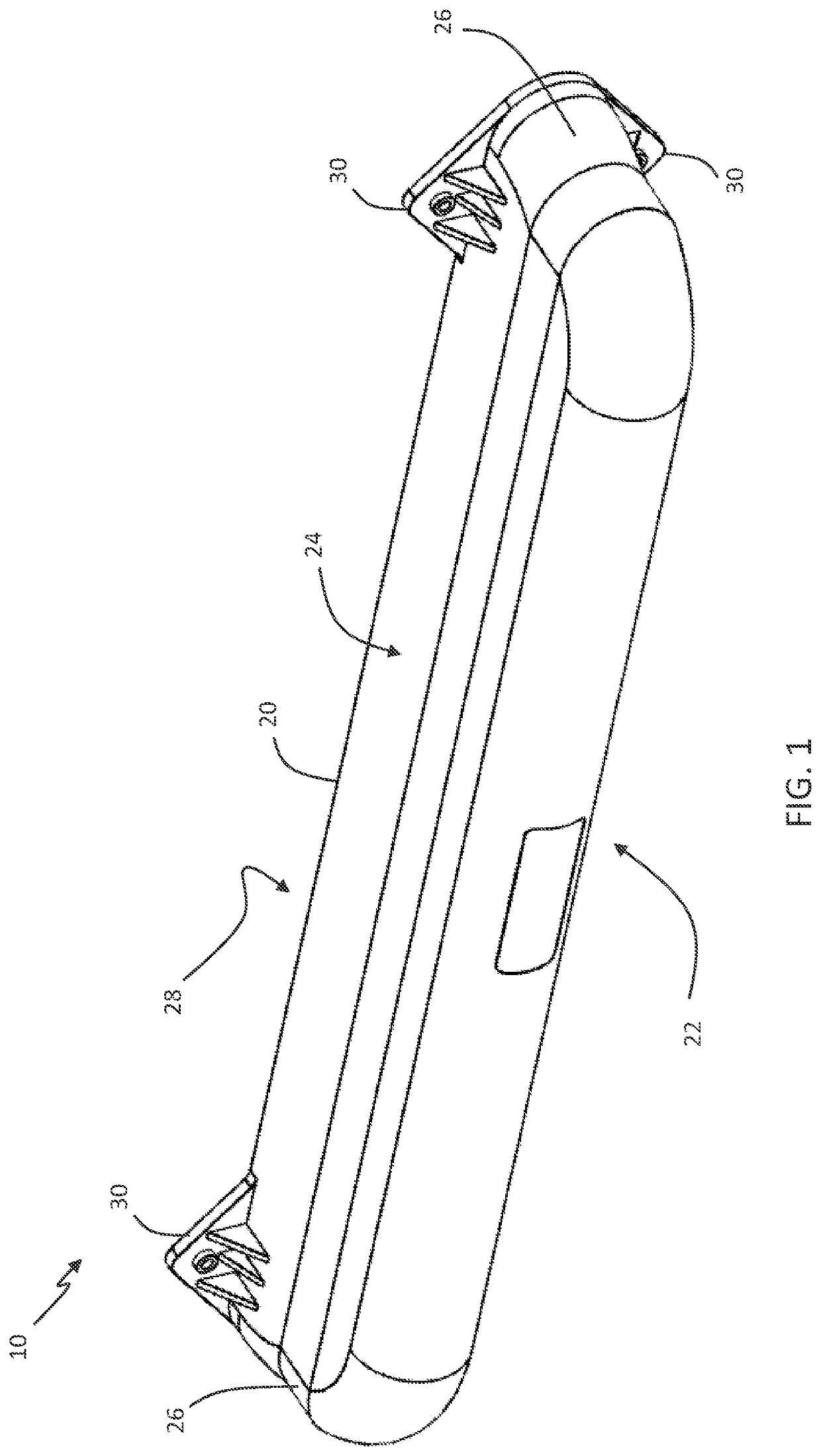
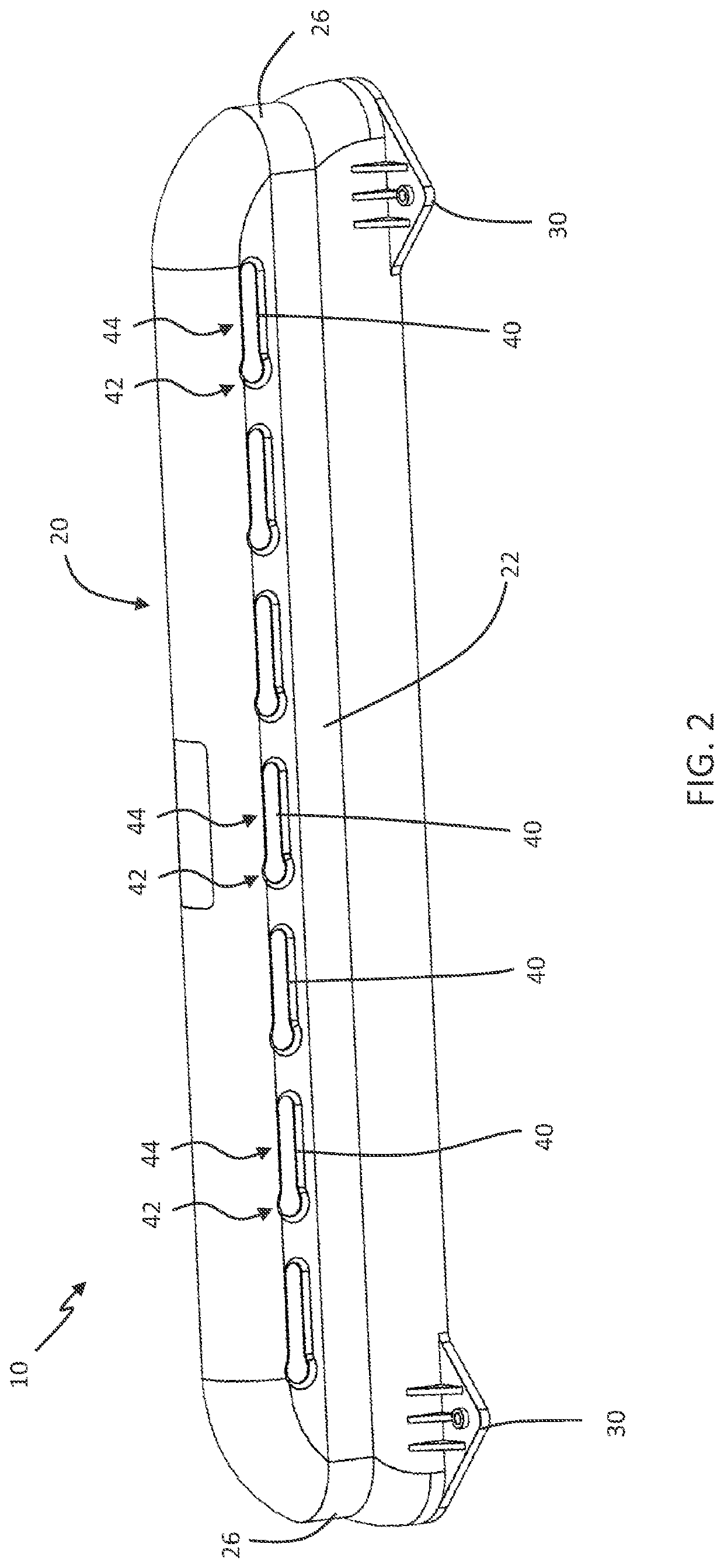
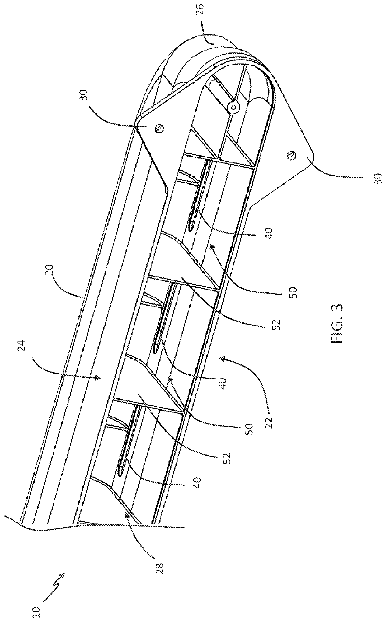
[0018]To overcome the problems in the field of storing pneumatic tools, the subject disclosure is directed to a pneumatic tool holder apparatus which allows for storage of pneumatic tools in such a manner to prevent dust or other debris from entering the interior of the tool and causing damage to it. FIGS. 1, 2, and 3 are top-view, bottom view, and rear-view illustrations, respectively, of the pneumatic tool holder apparatus 10, in accordance with a first exemplary embodiment of the present disclosure.

[0019]With reference to FIGS. 1-3, the pneumatic tool holder apparatus 10 has a housing 20, which is generally formed as a substantially unitary structure with a bottom plate 22, a top plate 24, and side portions 26, all connected or formed to one another. In a normal working orientation of the apparatus 10, the apparatus 10 is mounted with a rear portion 28 thereof positioned against a mounting structure, such as a wall, such that the bottom plate 22 of the housing 20 is positioned fa...


PUM


Abstract

A pneumatic tool holder apparatus and related methods of storing pneumatic tools are disclosed. The pneumatic tool holder apparatus has a housing having a bottom plate. A plurality of keyholes is formed in the bottom plate. Each of the plurality of keyholes have an enlarged side and a non-enlarged side, where the enlarged side is sized to receive an end of a pneumatic tool coupling device and the non-enlarged side is sized smaller than a collar on the end of the pneumatic tool coupling device. A plurality of interior compartments is formed within the housing. Each interior compartment corresponds to one of the plurality of keyholes. When the end of the pneumatic tool coupling device is inserted through a keyhole and into an interior compartment, the interior compartment prevents debris from gaining access to a pneumatic interior of a pneumatic tool.

Description

CROSS REFERENCE TO RELATED APPLICATION[0001]This application claims benefit of U.S. Provisional Application Ser. No. 63 / 081,116 entitled, “Pneumatic Tool Holder” filed Sep. 21, 2020, the entire disclosure of which is incorporated herein by reference.FIELD OF THE DISCLOSURE[0002]The present disclosure is generally related to a tool holder and more particularly is related to a pneumatic tool holder.BACKGROUND OF THE DISCLOSURE[0003]Pneumatic tools operate using a pressurized air supply which is transferred to the tool with a hose, tube, or similar structure. Commonly, the pneumatic tool connects to the supply hose with a coupling that allows the user to easily couple and decouple the pneumatic tool from the supply hose. These couplings may be referred to as a ‘quick coupling’ and they often have a male portion which is insertable into a receiver, the connection of which is controlled through a spring-biased cylindrical sleeve which holds the male portion in the receiver and can be pul...

Claims


Application Information

Patent Timeline
IPC IPC(8): B25H3/00B25H3/04
CPCB25H3/006B25H3/04
Inventor ELEFTHERIOU, GEORGE
Owner ELEFTHERIOU GEORGE
Why Eureka
Try Eureka