Power amplifying circuit

a power amplifier and circuit technology, applied in amplifiers, amplifier types, amplifiers with semiconductor devices/discharge tubes, etc., can solve the problems of imbalance between differential signals received by transformers, shift (imbalance) from ideal phase difference and amplitude difference between differential signals

Pending Publication Date: 2022-03-10
MURATA MFG CO LTD
View PDF0 Cites 1 Cited by
  • Summary
  • Abstract
  • Description
  • Claims
  • Application Information

AI Technical Summary

Benefits of technology

[0008]A power amplifying circuit according to an aspect of the present disclosure includes a first amplifier, a second amplifier, a transformer, and a capacitance element. The first amplifier amplifies a first signal of differential signals. The second amplifier amplifies a second signal of the differential signals. The transformer has a first winding and a second winding. The first winding has a first end connected to the first amplifier and has a second end connected to the second amplifier. The second winding has a first end connected to an un...

Problems solved by technology

In a power amplifying circuit using a transformer, parasitic capacitance, which occurs between the primary winding and the secondary winding of the transformer, causes a shift (imbalance) from the ideal phase difference ...

Method used


Image

  • Power amplifying circuit
  • Power amplifying circuit
  • Power amplifying circuit

Examples


Embodiment Construction

[0030]Embodiments of the present disclosure will be described in detail below by referring to the drawings. Identical components are designated with identical reference characters, and repeated description will be avoided as much as possible.

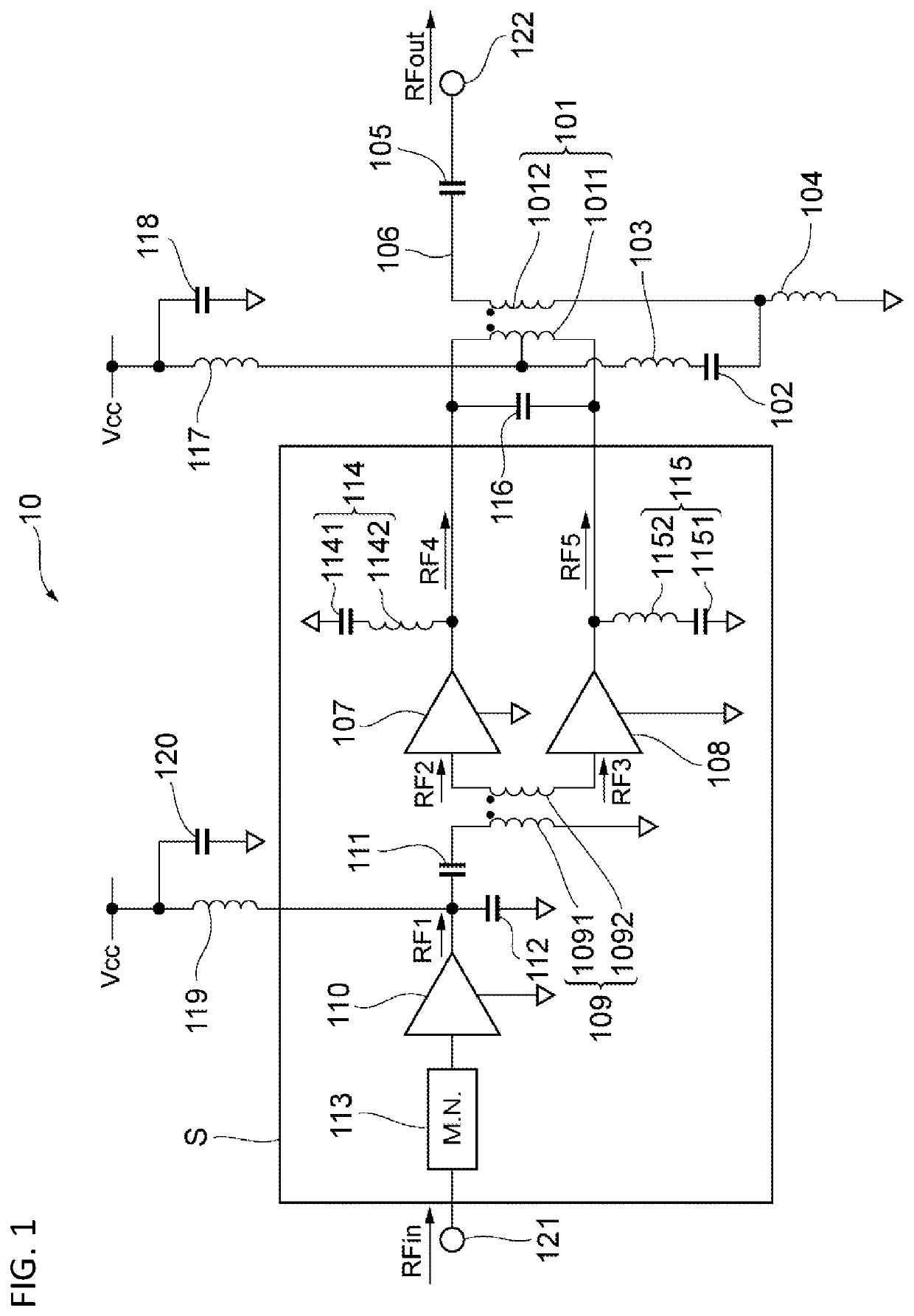
[0031]A first embodiment will be described. FIG. 1 is a circuit diagram of a power amplifying circuit 10 according to the first embodiment. The power amplifying circuit 10 includes a transformer 101, capacitors 102, 105, 111, 116, 118, and 120, inductors 103, 104, 117, and 119, amplifiers 107, 108, and 110, a matching circuit 113, and termination circuits 114 and 115.

[0032]The transformer 101 has a primary winding 1011 (first winding) and a secondary winding 1012 (second winding). The primary winding 1011 is electromagnetically coupled to the secondary winding 1012. The primary winding 1011 is connected, at its first end, to the output of the amplifier 107, and is connected, at its second end, to the output of the amplifier 108. The secondary wi...


PUM


Abstract

A power amplifying circuit includes a first amplifier, a second amplifier, a transformer having a primary winding and a secondary winding, and a capacitor. The first amplifier amplifies a signal which is one of differential signals. The second amplifier amplifies a signal which is the other of the differential signals. The primary winding is connected, at its first end, to the first amplifier, and is connected, at its second end, to the second amplifier. The secondary winding is connected, at its first end, to an unbalanced line through which an unbalanced signal is transmitted, and is connected, at its second end, to the ground. The secondary winding is electromagnetically coupled to the primary winding. The capacitor is connected, at its first end, to the midpoint of the primary winding, and is connected, at its second end, to the ground.

Description

CROSS REFERENCE TO RELATED APPLICATION[0001]This application claims priority from Japanese Patent Application No. 2020-149392 filed on Sep. 4, 2020. The content of this application is incorporated herein by reference in its entirety.BACKGROUND OF THE DISCLOSURE1. Field of the Disclosure[0002]The present disclosure relates to a power amplifying circuit.2. Description of the Related Art[0003]In communication using mobile units such as a cellular phone, power amplifying circuits, which amplify radio frequency (RF) signals, are used. Higher efficiency is required for power amplifying circuits. To achieve higher efficiency in power amplifying circuits, a power amplifying circuit, which performs amplification using differential signals, is used.[0004]U.S. Pat. No. 10,411,662 describes a power amplifying circuit using a transformer to combine differential signals which have been amplified by amplifiers. In the power amplifying circuit described in U.S. Pat. No. 10,411,662, the primary wind...

Claims


Application Information

Patent Timeline
IPC IPC(8): H03F3/21H03F3/30H03F3/193H03F1/02
CPCH03F3/21H03F3/3098H03F2200/451H03F1/0288H03F2200/541H03F3/193H03F3/211H03F3/45071H03F1/02
Inventor HONDA, YURITANAKA, SATOSHI
Owner MURATA MFG CO LTD
Why Eureka
Try Eureka