
3D printer and printing system

a printing system and three-dimensional technology, applied in the field of three-dimensional (3d) printers and printing systems, can solve the problems of limited detailed output, limited application of high-resolution lcd, and shorten the life of the printer, so as to reduce energy consumption, improve contrast ratio, and reduce power consumption.

Inactive Publication Date: 2022-03-10
RYUJIN LAB INC
View PDF0 Cites 2 Cited by
  • Summary
  • Abstract
  • Description
  • Claims
  • Application Information

AI Technical Summary

Benefits of technology

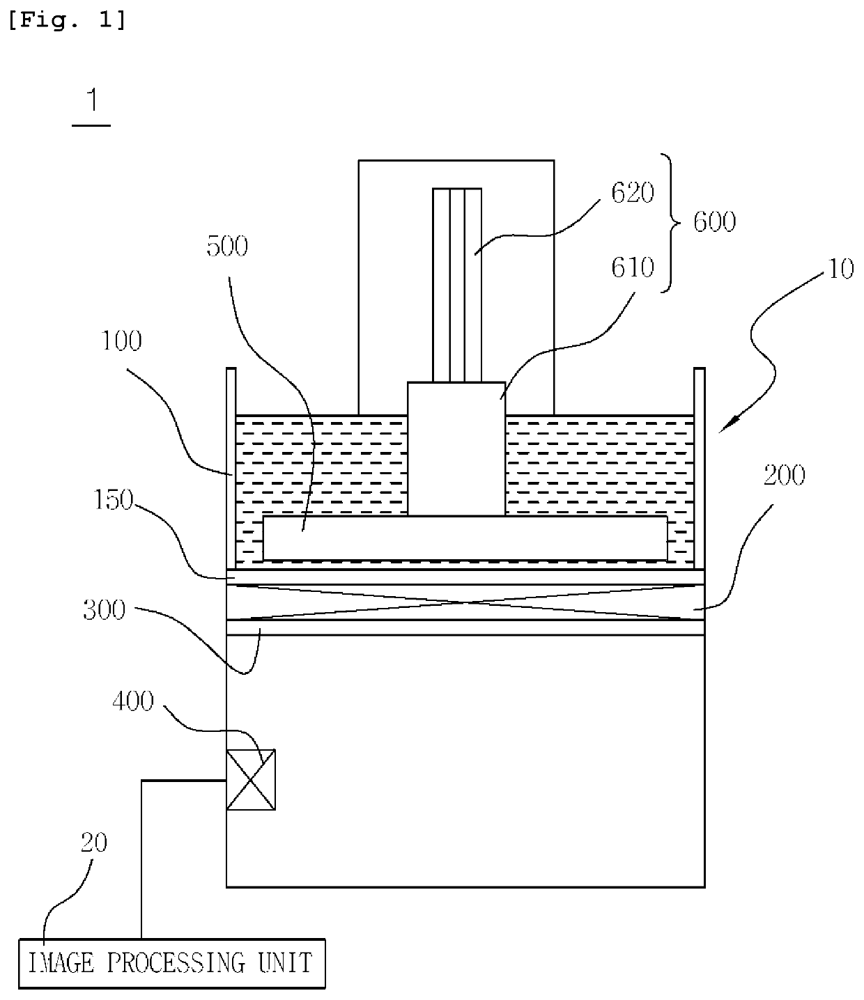
The technology presented in this patent reduces power consumption and improves output quality by selectively emitting light only onto the necessary region of a tomographic image. This improves the contrast ratio and minimizes the surrounding curing phenomenon. The technology also helps to improve the lifespan of the LEDs and LCDs used in the process, avoiding the issue of shortened lifespan caused by excessive light radiation. Additionally, the technology avoids the need for a large amount of light and power, making it easier to manufacture large-area 3D printers.

Problems solved by technology

First, they are inefficient due to the high energy consumption thereof;
Second, there is a limitation to detailed output as a surrounding curing phenomenon occurs due to the leakage of light from the LCD;
Third, when a high-resolution LCD having a smaller aperture ratio than a low-resolution LCD in the same area is used, the lifespan is shortened due to an increase in the fatigue of the LCD attributable to the LED light source, so that there is a limitation to the application of the high-resolution LCD;
Fourth, it is necessary to improve the lifetime of the LED which is always in an ON state and the lifetime of the LCD where light is radiated in an overall area; and
Fifth, when a large-area 3D printer is manufactured, the amount of light must be increased in proportion to the area and accordingly power increases proportionally, so that there is a limitation to the manufacture of the large-area 3D printer.
However, the related art described above has problems in that energy consumption is high and lifespan is shortened because the light source is always in an ON state.

Method used


Image

  • 3D printer and printing system
  • 3D printer and printing system
  • 3D printer and printing system

Examples


Embodiment Construction

[0038]Various embodiments will be described in detail below with reference to the accompanying drawings. The following embodiments may be modified to various different forms and then practiced. In order to more clearly illustrate features of the embodiments, detailed descriptions of items that are well known to those having ordinary skill in the art to which the following embodiments pertain will be omitted. Furthermore, in the drawings, portions unrelated to descriptions of the embodiments will be omitted. Throughout the specification, like reference symbols will be assigned to like portions.

[0039]Throughout the specification, when one component is described as being “connected” to another component, this includes not only a case where the one component is ‘directly connected’ to the other component but also a case where the one component is ‘connected to the other component with a third component arranged therebetween.’ Furthermore, when one portion is described as “including” one...


PUM

PropertyMeasurementUnit
light emission areaaaaaaaaaaa
areaaaaaaaaaaa
widthaaaaaaaaaa

Abstract

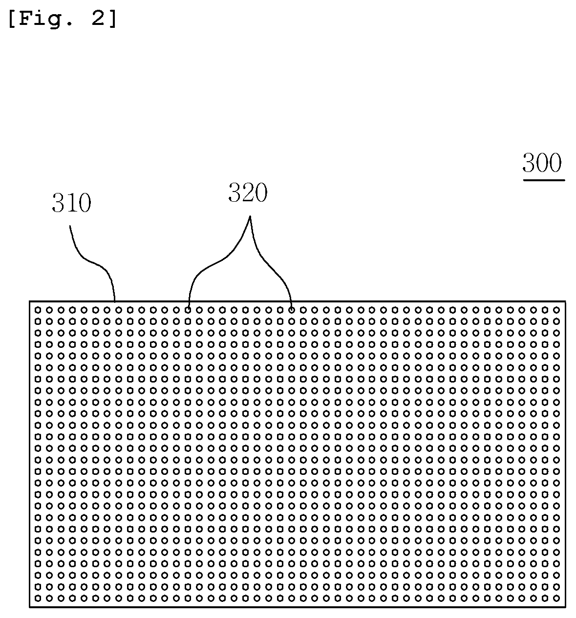
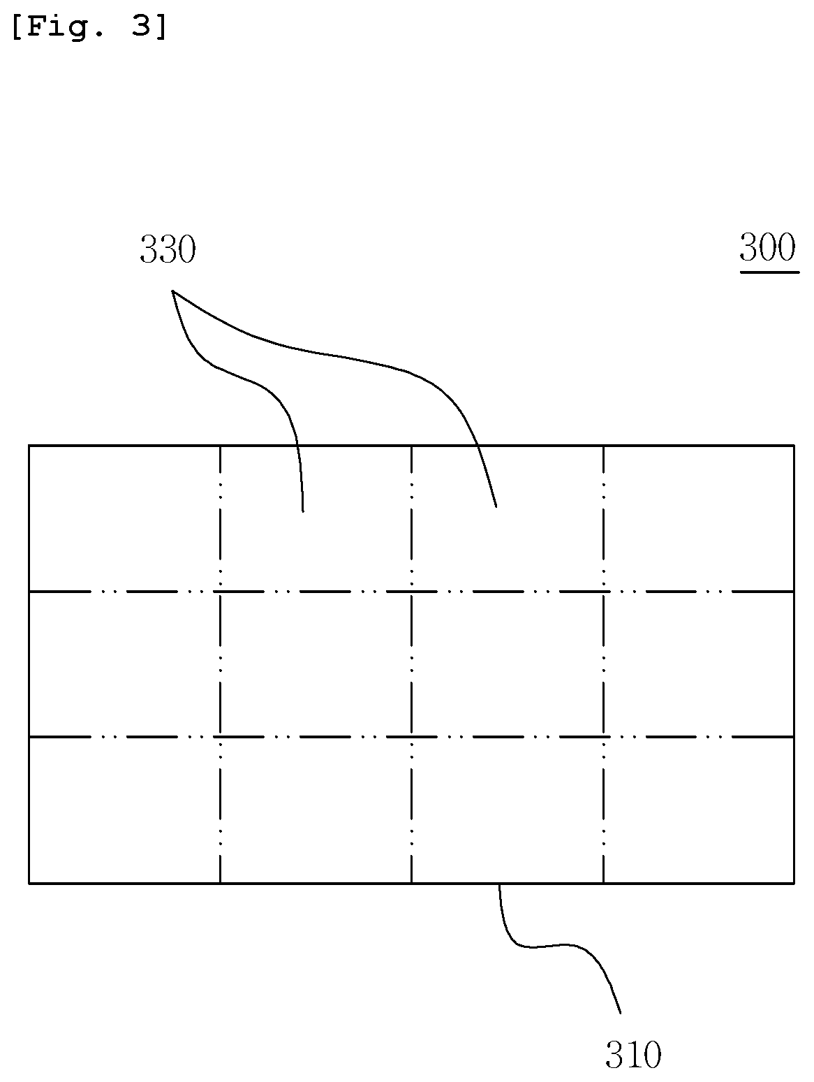
Proposed are a 3D printer and a printing system capable of selectively radiating backlight only onto an area corresponding to a single layer of an output molded object. The 3D printer includes: a resin accommodation part configured to accommodate a photocurable resin; an LCD unit configured to cure the photocurable resin by radiating light corresponding to a tomographic image onto the resin accommodation part; an LED backlight unit configured to provide backlight to the LCD unit in such a manner as to turn on the backlight in a region where the tomographic image is present and turn off the backlight in the remaining region where the tomographic image is not present in conjunction with an image signal from the LCD unit; and a control unit configured to control the light emission area of the LED backlight unit based on the image signal from the LCD unit.

Description

TECHNICAL FIELD[0001]The embodiments disclosed herein relate to a three-dimensional (3D) printer and a printing system, and more particularly to a 3D printer and a printing system that are capable of selectively radiating backlight only onto an area corresponding to a single layer of an output molded object.[0002]Background Art In general, a 3D printer (a three-dimensional molding machine) is a technology that uses 3D information of an object composed of a digital file, structures (slices) the object into considerably thin layers, and then stacks a material layer by layer based on this information, thereby implementing an actual molded object.[0003]Such 3D printers can be basically classified into a VAT Photopolymerization type and an FDM (FFF) type.[0004]Among these types of technologies, the VAT Photopolymerization-type technology is a technology that performs 3D printing using a photocurable resin that is cured when exposed to light, such as a resin. It is a technology that forms...

Claims


Application Information

Patent Timeline
Patent Type & Authority Applications(United States)
IPC IPC(8): B29C64/277B33Y30/00B33Y50/02B29C64/393
CPCB29C64/277B29C64/393B33Y50/02B33Y30/00B29C64/129B29C64/286B33Y10/00B29C64/282
Inventor PARK, SEONG JINLEE, HONG JOOKIM, KIHYUNG
Owner RYUJIN LAB INC
Learn More