
Optical mammograph using near-infrared in diffuse reflectance geometry

a near-infrared and optical technology, applied in the field of mammographic imaging devices, can solve the problems of preventing the continued use of said devices for monitoring the evolution of disease, low specificity and low sensitivity, and subject to operation errors

Pending Publication Date: 2022-02-24
CONSEJO NAT DE INVESTIGACIONES CIENTIFICAS Y TECH CONICET +1
View PDF14 Cites 0 Cited by
  • Summary
  • Abstract
  • Description
  • Claims
  • Application Information

AI Technical Summary

Benefits of technology

This patent is about a new device that can take pictures of breast tissue without needing to compress it. It uses a special technique called diffuse reflectance geometry to get rid of unwanted noise from the images. The device can also analyze the images to help with diagnostics. Overall, this technology solves problems that were previously associated with taking mammograms.

Problems solved by technology

The main drawback of known devices used for mammographies is that they present a relatively low specificity and low sensitivity.
Furthermore, these devices may identify some abnormality that may seem to be a tumor but that may end up not being one, which is described as a false positive (low specificity).
Devices most widely used nowadays for detecting inhomogeneities in breast tissue or mammographies use x ray ionizing radiation, which prevents the continued use of said devices for monitoring evolution of disease due to radiation exposition.
Furthermore, said devises usually imply patient's breasts being compressed, which is quite a traumatic experience for patients in general.
However, linear CCD arrangements that measure luminous intensity line to line are used, besides being a slow process (limited by the speed at which the measuring head may be manually moved), subject to operation errors.
Furthermore, this device does not produce a full 2D-image of the area to be explored in just one use.
However, large LED sources are used in this device, which prevents the obtention of in-depth information and only registers a map of the surface.
Moreover, in the case of breasts, compression between plates is required.

Method used


Image

  • Optical mammograph using near-infrared in diffuse reflectance geometry
  • Optical mammograph using near-infrared in diffuse reflectance geometry
  • Optical mammograph using near-infrared in diffuse reflectance geometry

Examples


Embodiment Construction

[0045]The present invention will be described in further detail below, with reference to the accompanying figures that illustrate exemplary embodiments of the invention, which must not be interpreted as limiting.

[0046]The same reference numbers are used in each figure for each element of the device of the invention.

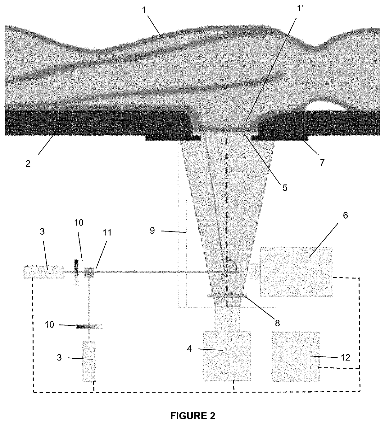
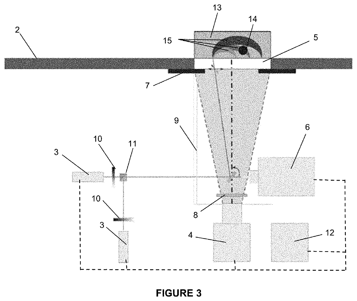
[0047]FIG. 1 shows a simplified schematic view of an embodiment of the device of the present invention, wherein a patient 1 and her breasts 1′, a stretcher 2, laser-light producing means 3 for producing laser light beams, light-sensing and imaging means 4 for sensing light and producing images and a transparent window 5 can be observed.

[0048]In said FIG. 1, the patient 1 can be observed in a decubito prono position on the stretcher 2 having her breasts resting on the transparent window 5. The use of the transparent window 5 avoids compression of the breast between two plates, which is typical of traditional mammographic devices, and patient 1 comfort is substantially impr...


PUM

PropertyMeasurementUnit
depthsaaaaaaaaaa
transparentaaaaaaaaaa
wavelengthaaaaaaaaaa

Abstract

A mammographic imaging device for analysis and detection of possible inhomogeneities in breast tissue of a patient using laser light in the near-infrared in diffuse reflectance geometry, includes a patient horizontal support comprising at least one transparent window in its cross-section and a measuring mechanism below the at least one transparent window and carried by said support. The measuring mechanism includes a laser-light producing mechanism for producing laser light beams in the near-infrared, a directing mechanism for directing said laser light beams towards the at least one transparent window, at least one wavelength filter, a light-sensing and imaging mechanism for sensing light and producing images and a controlling, processing and image-normalizing unit for controlling, processing and normalizing images.

Description

FIELD OF THE INVENTION[0001]This invention relates to a mammographic imaging device for analysis and detection of possible inhomogeneities in breast tissue that may be caused by different neoplastic pathologies, using near-infrared laser in diffuse reflectance geometry.BACKGROUND OF THE INVENTION[0002]It is well known that mammographies may save lives if breast cancer is detected early on. For this purpose, there exist several devices for analyzing breast tissue and detecting inhomogeneities, should there be any.[0003]The main drawback of known devices used for mammographies is that they present a relatively low specificity and low sensitivity. Normal breast tissue may hide a tumor, which may not be perceived by such devices, which provides a diagnosis described as a false negative (low sensitivity). Furthermore, these devices may identify some abnormality that may seem to be a tumor but that may end up not being one, which is described as a false positive (low specificity).[0004]De...

Claims


Application Information

Patent Timeline
Patent Type & Authority Applications(United States)
IPC IPC(8): G06T7/00A61B5/00H04N5/225G06T7/73G06T7/33H04N5/232H04N5/238H04N23/75
CPCG06T7/0014A61B5/0091A61B5/0077A61B5/7203G06T2207/30068G06T7/74G06T7/337H04N5/23229H04N5/238H04N5/2256A61B5/704H04N23/80H04N23/56H04N23/75
Inventor PARDINI, PAMELA A.GARCÍA, HÉCTOR A.WAKS SERRA, MARÍA V.CARBONE, NICOLÁS A.IRIARTE, DANIELA I.BAEZ, GUIDO R.DI ROCCO, HECTOR O.POMARICO, JUAN A.
Owner CONSEJO NAT DE INVESTIGACIONES CIENTIFICAS Y TECH CONICET
Learn More