Belt Drive for a Weed Seed Destructor of a Combine Harvester

a combine harvester and drive technology, applied in mowers, agriculture tools and machines, agriculture, etc., can solve the problems of reducing the life and performance of the belt drive, reducing the capacity of the drive, and reducing the life of the belt. the effect of load reduction

Pending Publication Date: 2022-02-17
TRITANA INTPROP LTD
View PDF0 Cites 0 Cited by
  • Summary
  • Abstract
  • Description
  • Claims
  • Application Information

AI Technical Summary

Benefits of technology

[0023]In some cases the cords can be formed as individual cords each defining one cord length wrapped wholly around the belt in one continuous loop. In other cases the belts have only one cord wrapped continuously in a helical wrap so that the single cord forms all of the cord lengths. The helical wrap is applied at a pitch so as to place the cord lengths in the backing at a uniform pitch across the width of the belt. Thus the one cord is wound around the belt. Other belts have one cord per rib (because the cord is in the rib) and thus a 3 rib belt has 3 cords. The helical wrapping provides an efficiency and extra load carrying capacity which comes from the fact that engineers discount one half of the wrap on each side. Only once the cord has been wrapped around the belt one half of the circumference will it start to pull load.
[0048]There are 8 different standard cross sections that are utilized worldwide. V-rib belts are not as common but are used in high power capacity requirements. Limitations include less misalignment and they require a cleaner environment than standard v-belts. V-rib belts are not as sensitive as synchronous belts, however they are much quieter, can carry the same loads, are infinitely adjustable in length, can maintain a slip functionality to protect the drive in a spike load situation and can be used with a constant tension idler. Advantages of a constant tension drive include ease of installation and tensioning, higher bearing life with reduced loads due to a reduced duty cycle, run quieter and provide belt slip.
[0053]The arrangement of the present invention may provide one or more of the following features and advantages:
[0055]Provide a more power dense belt; a belt with cords packed more tightly together and spread uniformly across the width of the belt, so that more power can be transmitted in the same space.
[0071]This arrangement provides an improved drive construction which may provide advantages of reduced loads on the pulleys and belt.

Problems solved by technology

The most demanding drive may be the residue management driveline due to its requirement to process crop residue that may easily be threshed but is not yet fully dry or fit for processing.
In lower yielding crop areas of the world, aftermarket designers are able to utilize the extra capacity in the drives due to lower crop yields and thus lower system loads.
However, when adding components in high yielding, tough crop conditions that additional capacity is not available and significant cost is incurred to redesign and increase the capacity of the drives.
This often has a ripple effect as the increased size and weight of the sheaves increases the overhung load on the bearings, requiring increased bearings and with larger cross-sectional belt profiles more heat is generated in belt flex, reducing belt life and performance.
Synchronous belts are the most efficient belt available and the most power dense belt (meaning the cord density is arranged as tightly as possible), however they do not work well with misaligned sheaves, debris or shock loads.
These belts cannot slip to protect the drive or the object they are powering and can only be designed with a fixed or locked center.
They, however, do not have good cord or power density and operate at lower efficiency than a synchronous belt.

Method used


Image

  • Belt Drive for a Weed Seed Destructor of a Combine Harvester
  • Belt Drive for a Weed Seed Destructor of a Combine Harvester
  • Belt Drive for a Weed Seed Destructor of a Combine Harvester

Examples


Embodiment Construction

[0080]The combination of straw management system and weed seed destruction system is shown generally in for example U.S. Pat. No. 10,495,369 issued Dec. 3, 2019, the disclosure of which is incorporated herein by reference, to which reference may be made for further detail of features described only generally herein.

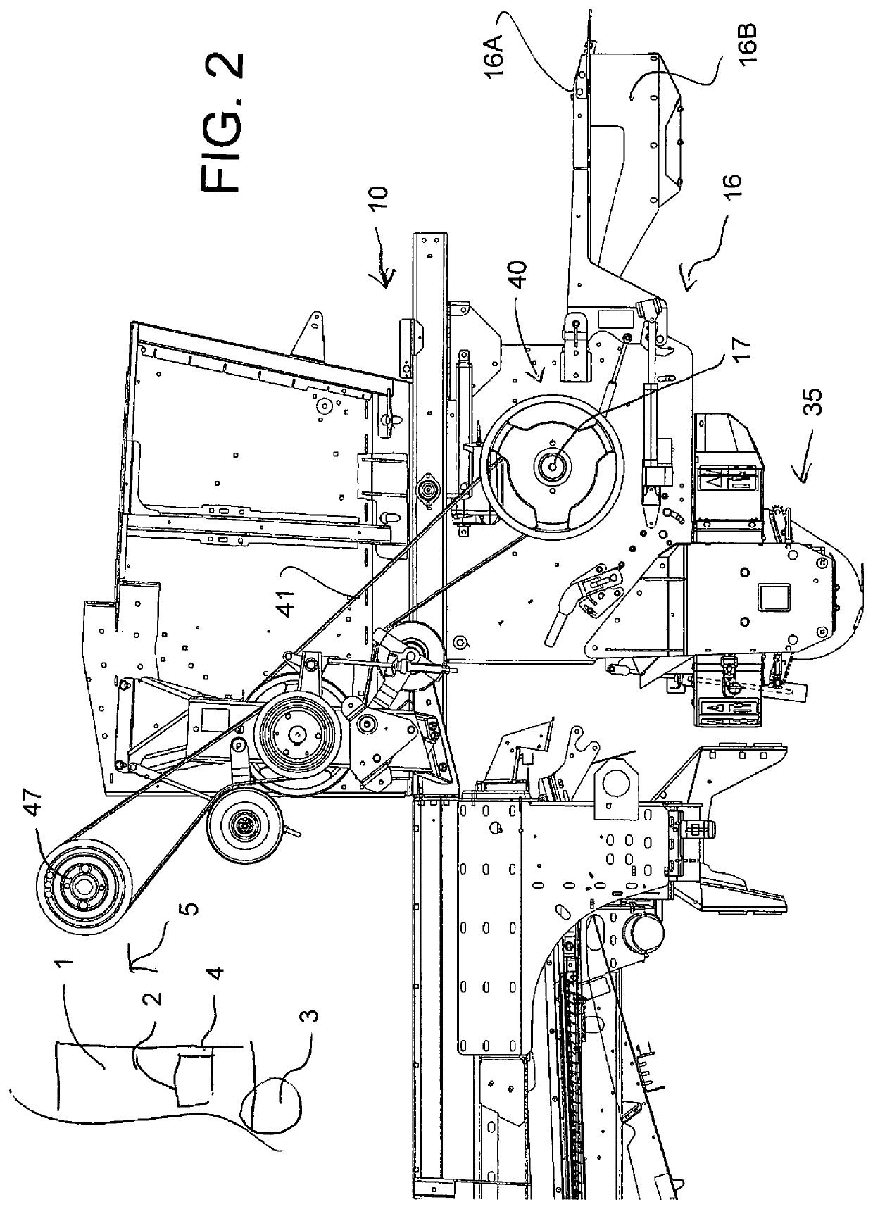
[0081]The apparatus herein is conventionally mounted on a combine harvester 1 carried on ground wheels 3 and including harvesting components of a conventional nature the rearmost one of which is the sieve 2 which discharges chaff and discarded seeds including weed seeds to the rear edge 4 of the sieve.

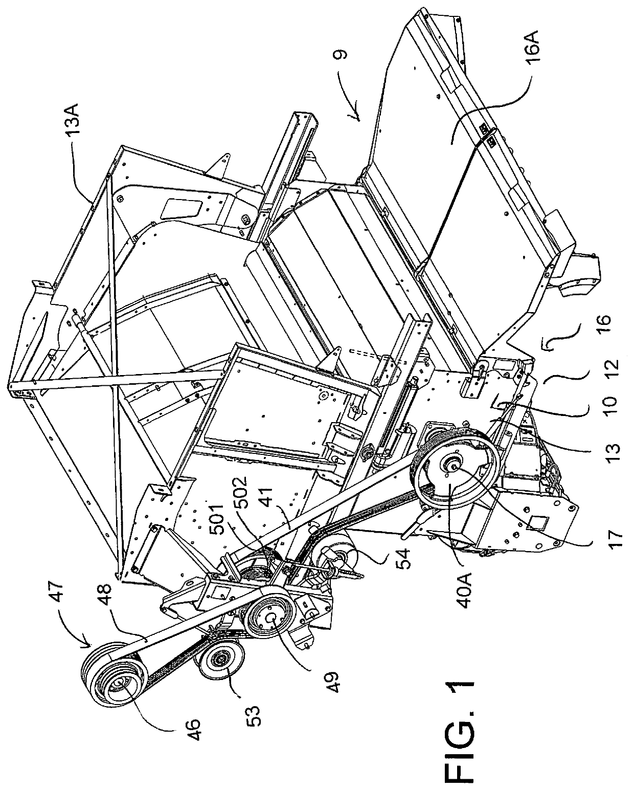
[0082]The combine harvester includes a chopper and discharge arrangement 9 shown in FIGS. 1 and 6 is basically as shown in U.S. Pat. No. 6,840,854 issued Jan. 11, 2005 of Redekop, the disclosure of which is incorporated herein by reference to which reference may be made for further detail of features described only generally herein. The chopper thus comprises a housing 10 de...


PUM


Abstract

Weed seeds are destroyed in the chaff from a combine harvester by repeated high speed impacts caused by a rotor mounted in one of a pair of side by side housings which accelerate the discarded seeds in a direction centrifugally away from the rotor onto a stator including angularly adjustable stator surfaces around the axis. The weed seed destructor is driven with a straw management system from an output shaft of the combine harvester so that the full power required for both passes through a belt which includes more than four longitudinally extending v-belt ribs and reinforcing cords located in a base band above the ribs at uniformly spaced positions across the width of the belt so that a replacement drive pulley on the output shaft has a width not significantly greater than a conventional output pulley which it replaces.

Description

[0001]This application claims the benefit under 35 USC 119 ( ) of Provisional application 63 / 065,609 filed Aug. 14, 2020, the disclosure of which is incorporated herein by reference.[0002]This invention relates to a weed seed destructor which can be attached to a combine harvester so that weed seeds in the discharged chaff can be devitalized before being spread onto the ground and particularly to a drive arrangement which provides a mechanical drive from a power take off shaft of the combine harvester to the destructor.BACKGROUND OF THE INVENTION[0003]Combine harvesters typically have many v-belt drives to transfer power from the engine to various components on the harvester. The most demanding drive may be the residue management driveline due to its requirement to process crop residue that may easily be threshed but is not yet fully dry or fit for processing. The residue management system driveline typically is driven from the main engine gearcase and can take over 50% of the engin...

Claims


Application Information

Patent Timeline
Patent Type & Authority Applications(United States)
IPC IPC(8): A01F29/04A01D41/12A01F12/40A01F12/56A01F29/14
CPCA01F29/04A01D41/1243A01F29/14A01F12/56A01F12/40
Inventor MAYERLE, DEAN
Owner TRITANA INTPROP LTD
Why Eureka
Try Eureka