
System and method for enhanced data analysis with specialized video enabled software tools for medical environments

a software tool and enhanced data technology, applied in the field of medical software tools, can solve the problems of poor visibility, surgeons must deal, and the number of challenges, and achieve the effect of facilitating equipment integration

Pending Publication Date: 2022-02-10
WADE JACK
View PDF23 Cites 0 Cited by
  • Summary
  • Abstract
  • Description
  • Claims
  • Application Information

AI Technical Summary

Benefits of technology

The patent describes a medical software tools platform that can be used in an operating room to help surgeons and their team with surgery. The platform is presented on a surgical display over an image stream from a surgical camera or other medical device. The image stream can include video or static images. The platform includes various medical software tools that can assist with the surgery, such as medically-oriented applications or widgets. The platform is controlled through a video switch that can allow multiple viewers to collaborate and update the visual information displayed. The technology helps provide context awareness and facilitate the integration of equipment in the operating room.

Problems solved by technology

While this brings many benefits to patients, it presents a number of challenges for the surgeon who must work within a very confined surgical compartment.
In particular, surgeons must deal with poor visibility, limited lighting, and a narrow viewing angle.
Because of their size, conventional medical imaging devices tend to have limited imaging resolution, often fail to provide more than one perspective of biological tissue, and due to visible lighting constraints, often fail to show differences in biological tissue.

Method used


Image

  • System and method for enhanced data analysis with specialized video enabled software tools for medical environments
  • System and method for enhanced data analysis with specialized video enabled software tools for medical environments
  • System and method for enhanced data analysis with specialized video enabled software tools for medical environments

Examples


Embodiment Construction

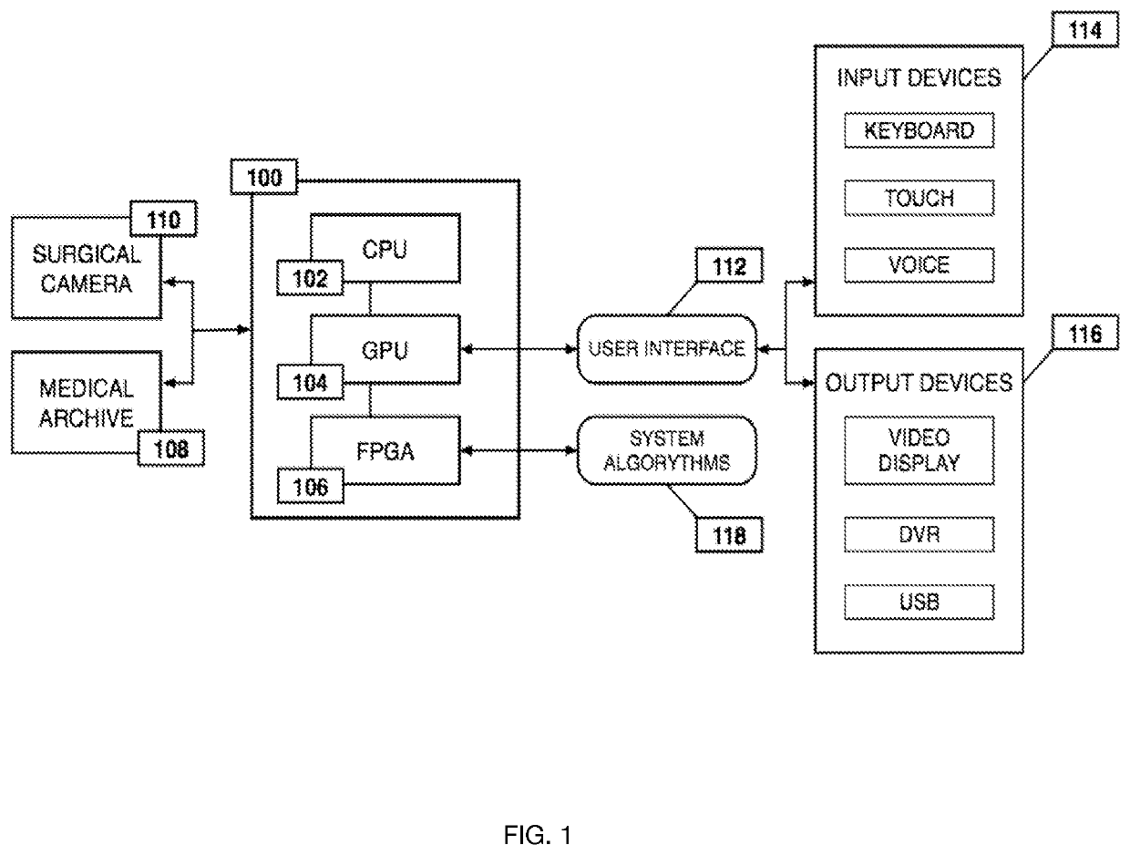
[0052]FIG. 1 is a block diagram illustrating an example of the overall processing system that may be used in implementing various features of embodiments of the disclosed technology. In accordance with the preferred embodiment of the present invention, the processing system 100 consists of processor elements such as: a central processing unit (CPU) 102; a graphics processing unit (GPU) 104; and a field programmable gate array (FPGA) 106. The processing system 100 may be used to retrieve and process raw data derived from a surgical camera 110 or a data storage device, such as a medical archive 108. The surgical camera 110 or medical archive 108 transmits a data stream to the processing system 100, whereby that data is processed by the CPU 102. The FPGA 106, connected to the CPU 102 and the GPU 104, simultaneously processes the received data by using a series of programmed system algorithms 118, thus functioning as an image clarifier within the processing system 100. The GPU 104 commu...


PUM


Abstract

Medical software tools platforms utilize a surgical display to provide access to specific medical software tools, such as medically-oriented applications or widgets, that can assist surgeons or surgical team in performing various procedures. In particular, an endoscopic camera may register the momentary rise in the optical signature reflected from a tissue surface and in turn transmit it to a medical image processing system which can also receive patient heart rate data and display relevant anomalies. Changes in various spectral components and the speed at which they change in relation to a source of stimulus (heartbeat, breathing, light source modulation, etc.) may indicate the arrival of blood, contrast agents or oxygen absorption. Combinations of these may indicate various states of differing disease or margins of tumors, and so forth. Also, changes in temperatures, physical dimensions, pressures, photoacoustic pressures and the rate of change may indicate tissue anomalies in comparison to historic values.

Description

PRIORITY CLAIMS[0001]This application is a continuation of U.S. patent application Ser. No. 16 / 694,711, filed on Nov. 25, 2019, which is a continuation of U.S. patent application Ser. No. 16 / 204,487, filed on Nov. 29, 2018, and issued as U.S. Pat. No. 10,517,689 on Dec. 31, 2019, which is a continuation of U.S. patent application Ser. No. 16 / 107,071, filed on Aug. 21, 2018, and issued as U.S. Pat. No. 10,687,914 on Jun. 23, 2020, which is a continuation of U.S. patent application Ser. No. 15 / 958,983, filed Apr. 20, 2018, and issued as U.S. Pat. No. 10,507,075 on Dec. 17, 2019, which is a continuation of U.S. patent application Ser. No. 15 / 789,948, filed Oct. 20, 2017, which is a continuation in part of U.S. patent application Ser. No. 15 / 652,031, filed Jul. 17, 2017, and issued as U.S. Pat. No. 10,433,917 on Oct. 8, 2019, which is a continuation in part of U.S. patent application Ser. No. 15 / 456,458, filed Mar. 10, 2017, and issued as U.S. Pat. No. 10,758,314 on Sep. 1, 2020, which ...

Claims


Application Information

Patent Timeline
IPC IPC(8): A61B90/00G06F3/0481A61B1/00A61B34/00A61B1/313G16H40/67H04N7/14G16H10/00G16H20/40G16H40/63G16H30/40
CPCA61B90/361H04L67/125A61B1/00011A61B34/25A61B1/3132A61B1/00009G16H40/67H04N7/147G16H10/00G16H20/40G16H40/63G16H30/40G06T2200/24G06T2207/30004G06F3/0481A61B1/000095A61B1/0005A61B5/0075A61B5/0084A61B5/0095A61B5/024A61B5/1032A61B2090/3612G16H10/60G16H50/20G16H50/70H04N7/183G16H80/00A61B2017/00203A61B90/30
Inventor WADE, JACK
Owner WADE JACK
Learn More