
Method and device for operating a laser material processing machine

Pending Publication Date: 2022-02-03
ROBERT BOSCH GMBH
View PDF0 Cites 0 Cited by
  • Summary
  • Abstract
  • Description
  • Claims
  • Application Information

AI Technical Summary

Benefits of technology

The patent text describes a method to reduce the number of experiments needed while also compensating for potential errors in the simulations. This can be done in a simple way and can help to quickly and accurately carry out the necessary experiments.

Problems solved by technology

Due to the very high intensity, the absorbed laser energy results in pulsed very rapid heating of the workpiece material, which results, on very short time scales and in a spatially very localized manner, in melt formation and also partial vaporization.
In the case of longer pulse durations and lower intensities, the drilled hole formation is clearly dominated by melt expulsion, which results in reduced precision with significantly higher productivity.
In the manufacturing method laser drilling, the process development is typically experimental in nature, because the numerous highly dynamic interacting physical effects presently are not able to be modeled with sufficient accuracy.
Reliable predictions of quality properties, for example, solidified melt deposits inside the drilled hole or also in the form of a burr at the drilled hole entry, damage to the drilled hole edge, or also the circularity of the drilled holes are presently not possible using these models.
Due to the very high intensity, the absorbed laser energy results in very rapid local heating of the workpiece materials, which results in a shared melt bath formation on short time scales and in a spatially very localized manner.
The resulting metallic splashes (so-called weld spatter) may result in a reduction of the component quality and / or may require production interruptions for cleaning the laser welding facility, which causes a significant increase of the manufacturing costs.
As in the case of laser drilling, the process development (process optimization with the goal of minimizing the weld spatter) is also very experimental in nature in the case of laser welding, because the numerous highly dynamic interacting physical effects are not able to be modeled with sufficient accuracy.
One challenge in the modeling in this case is that the workpiece characteristic data are often not known for the relevant pressures and temperatures.
However, a reliable prediction on quality properties, for example, solidified weld spatter, is not possible using these models.
Because there are many settable process parameters (which are often time-dependent and location-dependent), such as laser power, focus diameter, focus position, welding speed, laser beam inclination, circular path frequency, and process shielding gas, the optimization of the process parameters is a cumbersome process which requires very many experiments.
Because, on the one hand, many workpieces or components are required for these experiments and, on the other hand, the evaluation (manufacturing of the cross sections for measuring the weld seam geometry) is also complex, the number of the required experiments has to be reduced to a minimum.
Moreover, in practice the costs of the required production equipment are also decisive; with increasing flexibility of the variable parameters, the costs normally also rise.
Because there are many settable process parameters (e.g., pulse duration, focus position (time-dependent), focus size, pulse repetition frequency, circular path diameter (time-dependent), circular path frequency, incidence angle (time-dependent), drilling duration, pulse energy (time-dependent), wavelength, process gas type and pressure), which often also may be varied in a time-dependent manner, the optimization of the process parameters is a cumbersome process which requires very many experiments.
Because, on the one hand, many workpieces or components are required for these experiments and, on the other hand, the evaluation (in particular of the inner drilled hole shape) is also complex, the number of the required experiments has to be reduced to a minimum.
Because there are many settable process parameters (which are often dependent on time and location), such as laser power, focus diameter, focus position, welding speed, laser beam inclination, circular path frequency, and process shielding gas, the optimization of the process parameters is also a cumbersome process which requires very many experiments in the case of laser welding.
Because, on the one hand, many workpieces or components are required for these experiments and, on the other hand, the evaluation (manufacturing of cross sections for measuring the weld seam geometry) is also complex, it is desirable for the number of the required experiments to be reduced to a minimum.
Because the experiments are very complex, this noise normally may not be suppressed by numerous repetitions with the same input parameter set using subsequent averaging of the results.
It is unimportant with which uncertainty the models depict the process and how many of the quality criteria they describe.
In general, however, the prediction accuracy of the process models is limited.
In general, process models therefore may not replace physical experiments completely, but only partially.

Method used


Image

  • Method and device for operating a laser material processing machine
  • Method and device for operating a laser material processing machine
  • Method and device for operating a laser material processing machine

Examples


Embodiment Construction

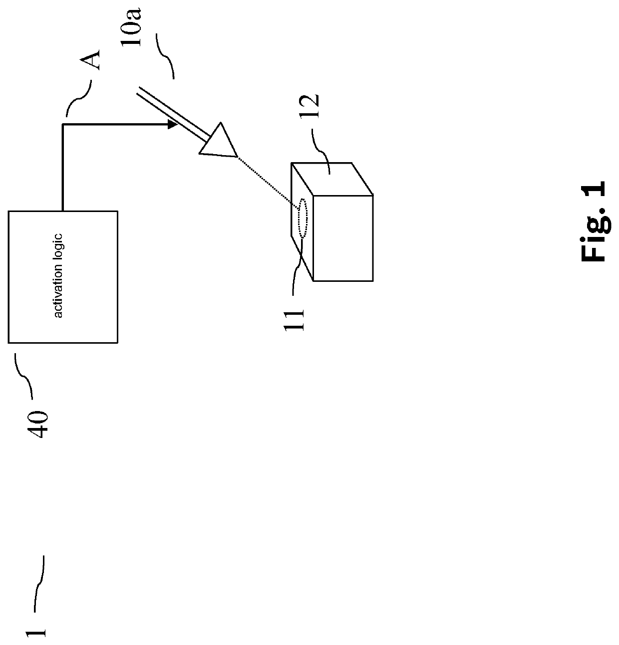
[0073]FIG. 1 schematically shows a structure of a laser drilling machine 1. An activation signal A is provided by an activation logic 40 to activate a laser 10a. The laser beam strikes a material piece 12, where it generates a drilled hole 11.

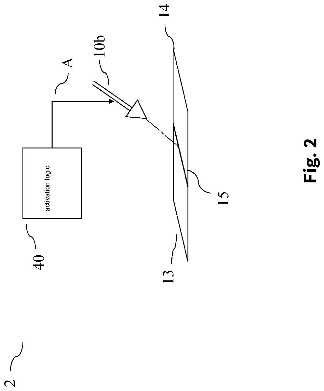
[0074]FIG. 2 schematically shows a structure of a laser welding machine 2. An activation signal A is also provided here by an activation logic 40 to activate a laser 10b. The laser beam strikes two material pieces 13, 14 and generates a weld seam 15 there.

[0075]A laser cutting machine (not shown) is also similarly possible.

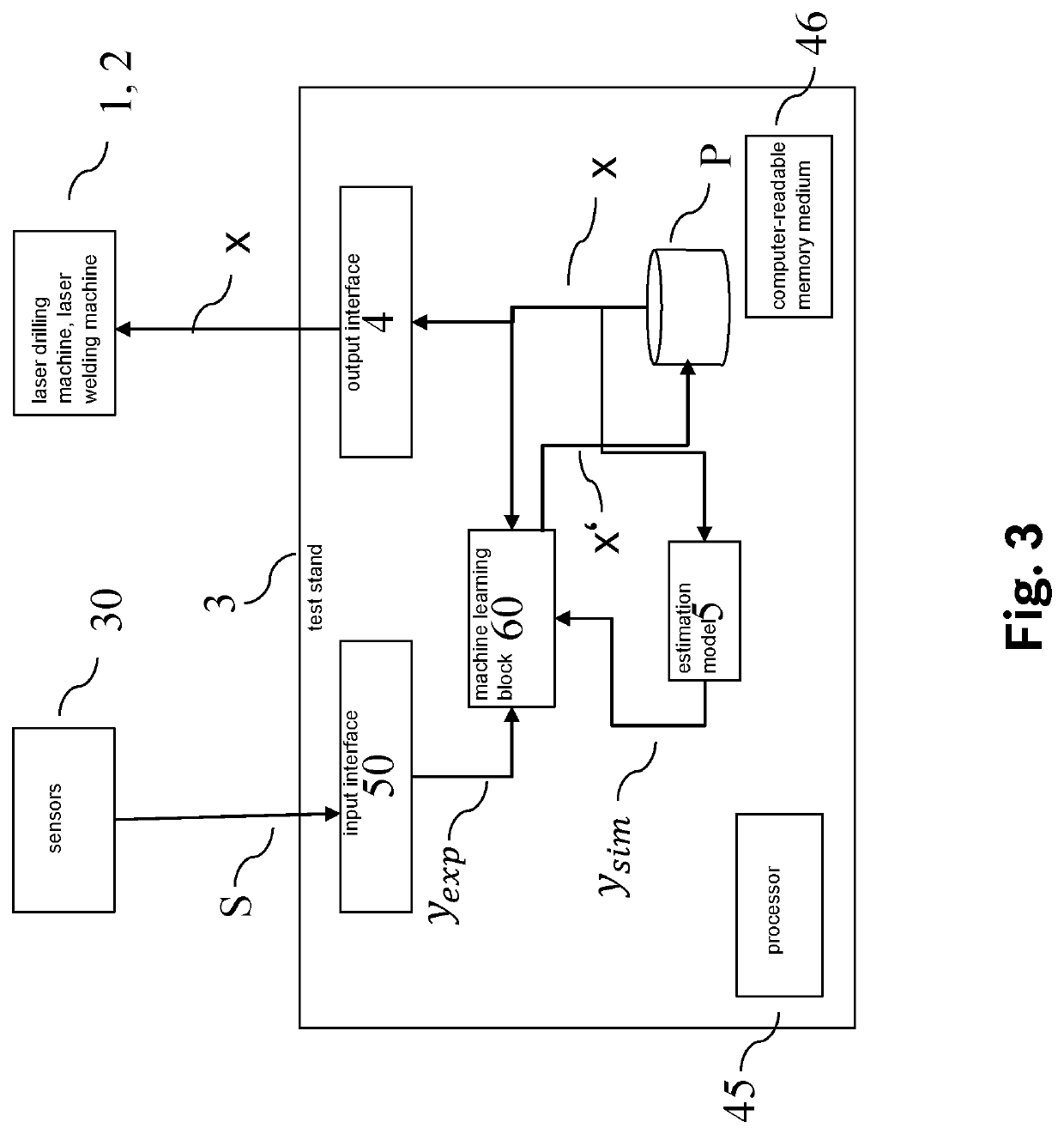
[0076]FIG. 3 schematically shows a structure of a test stand 3 for ascertaining optimum process parameters x. Present process parameters x are provided by a parameter memory P via an output interface 4 of the laser material processing machine, for example, laser drilling machine 1 or laser welding machine 2. This machine carries out the laser material processing as a function of these provided process parameters ϕ. Sensors 30...


PUM


Abstract

A computer-implemented method for operating a laser material processing machine. Process parameters are varied with the aid of Bayesian optimization until a result of the manufacturing, in particular the laser material processing, is sufficiently good. The Bayesian optimization is carried out with the aid of a data-based process model in a first phase, the data-based process model being trained as a function of estimated results. In a second phase, the data-based process model is trained as a function of the ascertained result resulting upon activation of the laser material processing machine.

Description

CROSS REFERENCE[0001]The present invention relates to a method for operating a laser material processing machine, a test stand, a computer program, and a machine-readable memory medium.BACKGROUND INFORMATION[0002]A method for operating a laser material processing machine with the aid of Gaussian process models and Bayesian optimization is described in German Patent Application No. DE 102020205967.5.[0003]Drilling using laser radiation is a manufacturing method for manufacturing drilled holes in greatly varying materials. The laser beam, which is pulsed and focused, for example, is applied to a workpiece. Due to the very high intensity, the absorbed laser energy results in pulsed very rapid heating of the workpiece material, which results, on very short time scales and in a spatially very localized manner, in melt formation and also partial vaporization.[0004]The molten material is expelled from the drilled hole by the process-related explosively generated vapor pressure and also lar...

Claims


Application Information

Patent Timeline
IPC IPC(8): B23K26/03B23K9/095G06N20/00
CPCB23K26/03G06N20/00B23K9/0953B23K26/382B23K26/702G06N20/10B23K31/006B23K31/125G06N7/01
Inventor KROSCHEL, ALEXANDERILIN, ALEXANDERMICHALOWSKI, ANDREASRIDDERBUSCH, HEIKOVINOGRADSKA, JULIATIGHINEANU, PETRUEIVAZI, ANNA
Owner ROBERT BOSCH GMBH
Learn More