Method and device for helping to position forks of a handling machine

a technology of forks and handling machines, which is applied in the direction of lifting devices, computer control, instruments, etc., can solve the problems of product loss, loss of time in the handling of loads, and the difficulty of inserting forks under the load to be handled, so as to achieve the effect of satisfying

Pending Publication Date: 2021-12-30
CAPRON MICHEL
View PDF0 Cites 1 Cited by
  • Summary
  • Abstract
  • Description
  • Claims
  • Application Information

AI Technical Summary

Benefits of technology

[0011]The present invention sets out to provide a method and a device which addresses all of the requirements expressed by the practitioners in load handling. To this end, the method and the device which devolves therefrom make it possible to effectively satisfy the constraints discussed above that the known assistance devices are not able to satisfy.

Problems solved by technology

The drivers of fork-lift handling machines are constantly confronted with the difficulty of inserting the forks under the load to be handled whether this load is placed on a pallet or on any other chocking means.
Very often, he or she has to search for his or her loads at height, then confronted with parallax issues.
This difficulty creates losses of time in the handling of the loads and sometimes the loads are affected, then provoking product losses.
These patents also include drawbacks, in particular:the installation of the device on the machine and the settings are neither easy nor rapid;the device is inadequately protected from possible collisions with the loads to be handled;the driver receives no information on the inclination value of the forks of his or her machine;with the light mark being activated in an uncommanded manner, the autonomy of the device is penalized when the latter is powered by batteries;the technology retained allows neither the operation of the method implemented to be adjusted easily, nor new functionalities to be added.

Method used


Image

  • Method and device for helping to position forks of a handling machine
  • Method and device for helping to position forks of a handling machine
  • Method and device for helping to position forks of a handling machine

Examples


Embodiment Construction

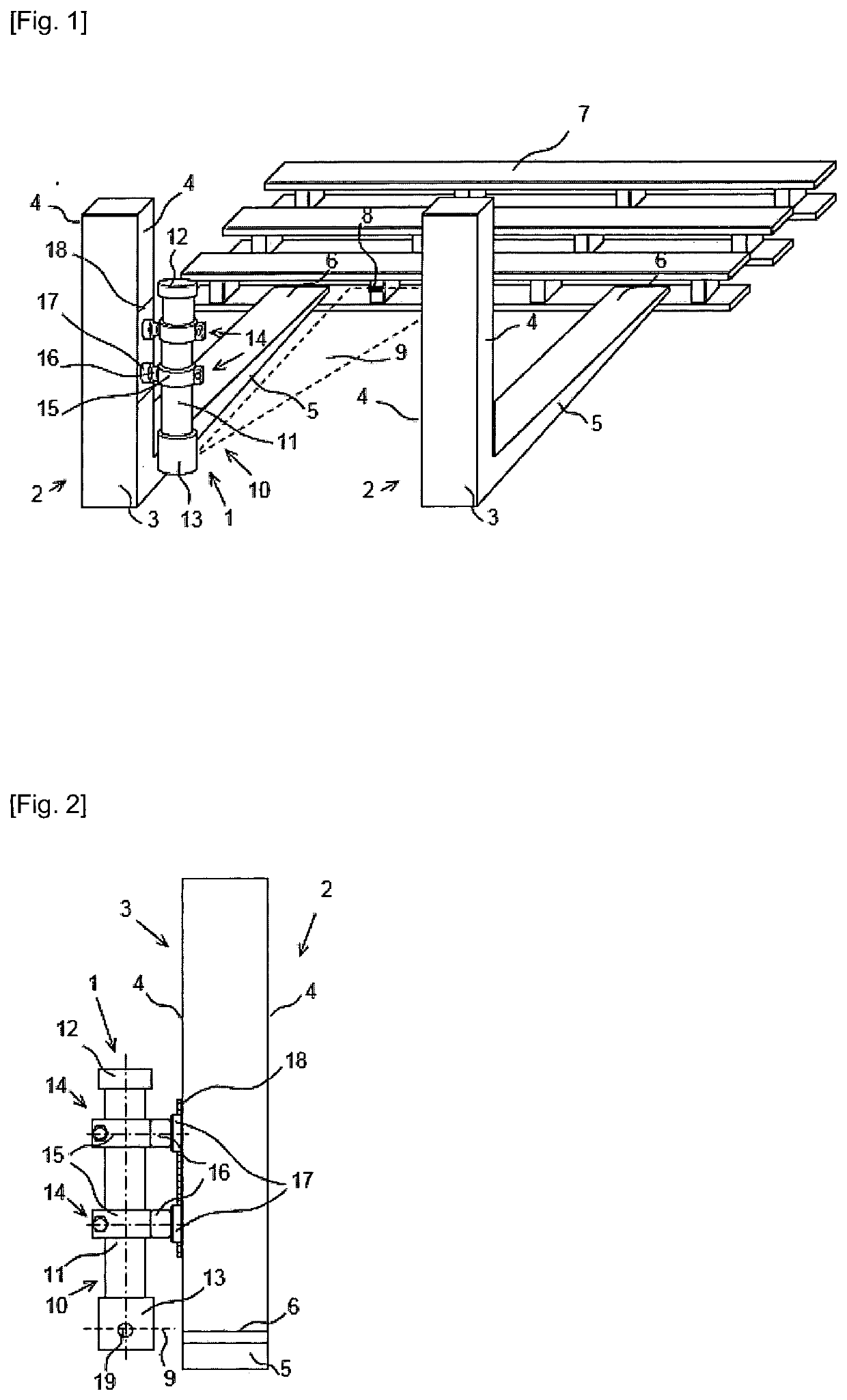
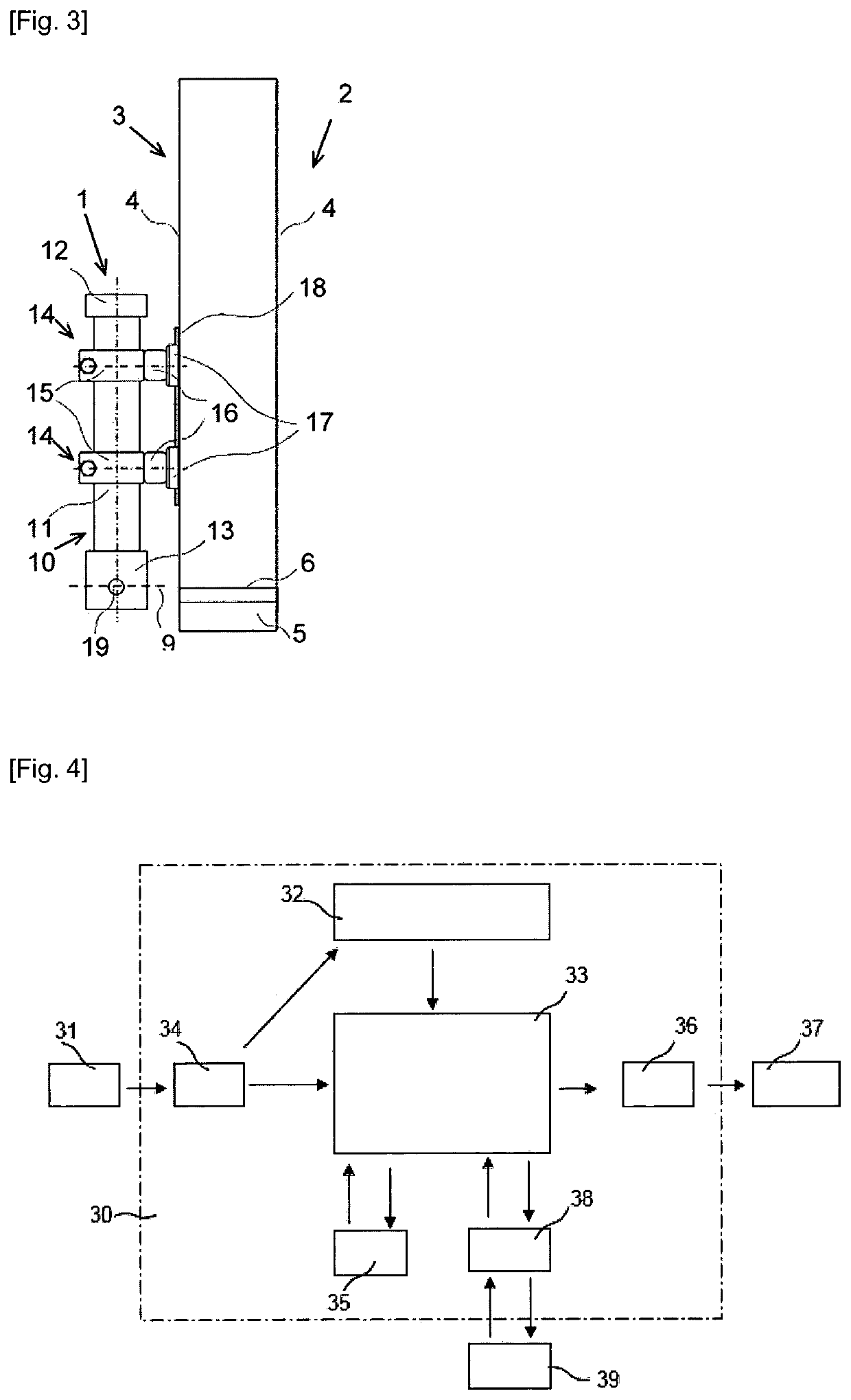
[0064]With reference to FIGS. 1, 2 and 3.

[0065]The device (1) of the invention, composed of a body (10) of elongate form, of two rapid ties (14) and of an indexing means (18), is placed on the lateral face (4) of the upright (3) of the fork (2). This is in fact a point where the device (1) is particularly protected from collisions with the loads (7) to be handled. According to other variants, not represented, the device (1) will be able to be placed elsewhere on the fork (2) and even more generally on any element secured to the forks (2) and in particular on the apron or the mast of the machine.

[0066]The body (10) is composed of a cylindrical hollow housing (11) closed by a top plug (12) and a bottom plug (13). The body (10) contains the electronic means which implements mainly an electrical battery (31), an accelerometer (32), a programmable microcontroller (33) and a module (37) for emitting a light beam (9). The removable top plug (12) allows access to and the replacement of the ...


PUM


Abstract

A method and device allowing a driver of a handling machine of the forklift type to position and introduce, in complete safety, the forks of the machine under a load to be handled. A light-beam that projects a luminous mark onto the load to be handled informs the driver of the relative position of the forks with respect to the load to be handled. The light-beam is activated and adjusted depending on the different steps of handling and inclination of the forks, which, for their part, are identified solely on the basis of the measurement of the acceleration acting on the forks. The device, which is installed quickly and protected effectively against collisions, has a high degree of operational autonomy. It improves working conditions and reduces product losses.

Description

TECHNICAL FIELD[0001]The present invention relates to a method for assisting in the positioning of the arms of forks of a fork-lift handling machine which, by means of a light beam projecting a light mark onto a load to be handled, informs the driver of said handling machine of the relative position of said arms of said forks with respect to said load to be handled to allow him or her to appropriately position said arms of said forks before inserting them, in total safety, under said load to be handled.[0002]It relates also to a device for assisting in the positioning of the arms of forks of a fork-lift handling machine which, by means of a light beam projecting a light mark onto a load to be handled, informs the driver of said handling machine of the relative position of said arms of said forks with respect to said load to be handled to allow him or her to appropriately position said arms of said forks before inserting them, in total safety, under said load to be handled, for the i...

Claims


Application Information

Patent Timeline
Patent Type & Authority Applications(United States)
IPC IPC(8): B66F9/075G05B19/4155
CPCB66F9/0755G05B2219/35414G05B2219/45049G05B19/4155
Inventor CAPRON, MICHEL
Owner CAPRON MICHEL
Why Eureka
Try Eureka