
Multi-layered coated electrode for lithium-ion battery

a lithium-ion battery and electrode technology, applied in the direction of electrode rolling/calendering, cell components, electrical equipment, etc., can solve the problems of delamination of coating, increase conductivity, and persisting manufacturing of li-ion battery cells including such electrodes, so as to maximize the energy density of a given li-ion battery cell, increase the duration, and increase the energy density

Active Publication Date: 2021-12-23
A123 SYSTEMS LLC
View PDF3 Cites 3 Cited by
  • Summary
  • Abstract
  • Description
  • Claims
  • Application Information

AI Technical Summary

Benefits of technology

The patent text discusses ways to increase the energy density of lithium-ion battery cells used in electric and hybrid-electric vehicles. One way to do this is to increase the coating weights on current collectors in the battery cells. However, this can result in increased direct current internal resistance (DCIR) at the beginning of life and during cycling. To address this, the text suggests reducing the amount of binder in the coatings and increasing the amount of conductive additive or active material in the coatings. This can lead to faster charging and higher power. The patent also mentions the use of silicon-based materials in anodes and specific cathode materials for achieving additional energy density increases.

Problems solved by technology

However, challenges persist in manufacturing Li-ion battery cells including such electrodes.
Such reduced adhesion may result in delamination of the coating from the current collector during formation of the electrode and the Li-ion battery cell including the electrode.
Further, trends in electrochemical performance may be balanced by the increased amount of conductive additive, which may increase conductivity and further decrease DCIR.

Method used


Image

  • Multi-layered coated electrode for lithium-ion battery
  • Multi-layered coated electrode for lithium-ion battery
  • Multi-layered coated electrode for lithium-ion battery

Examples


Embodiment Construction

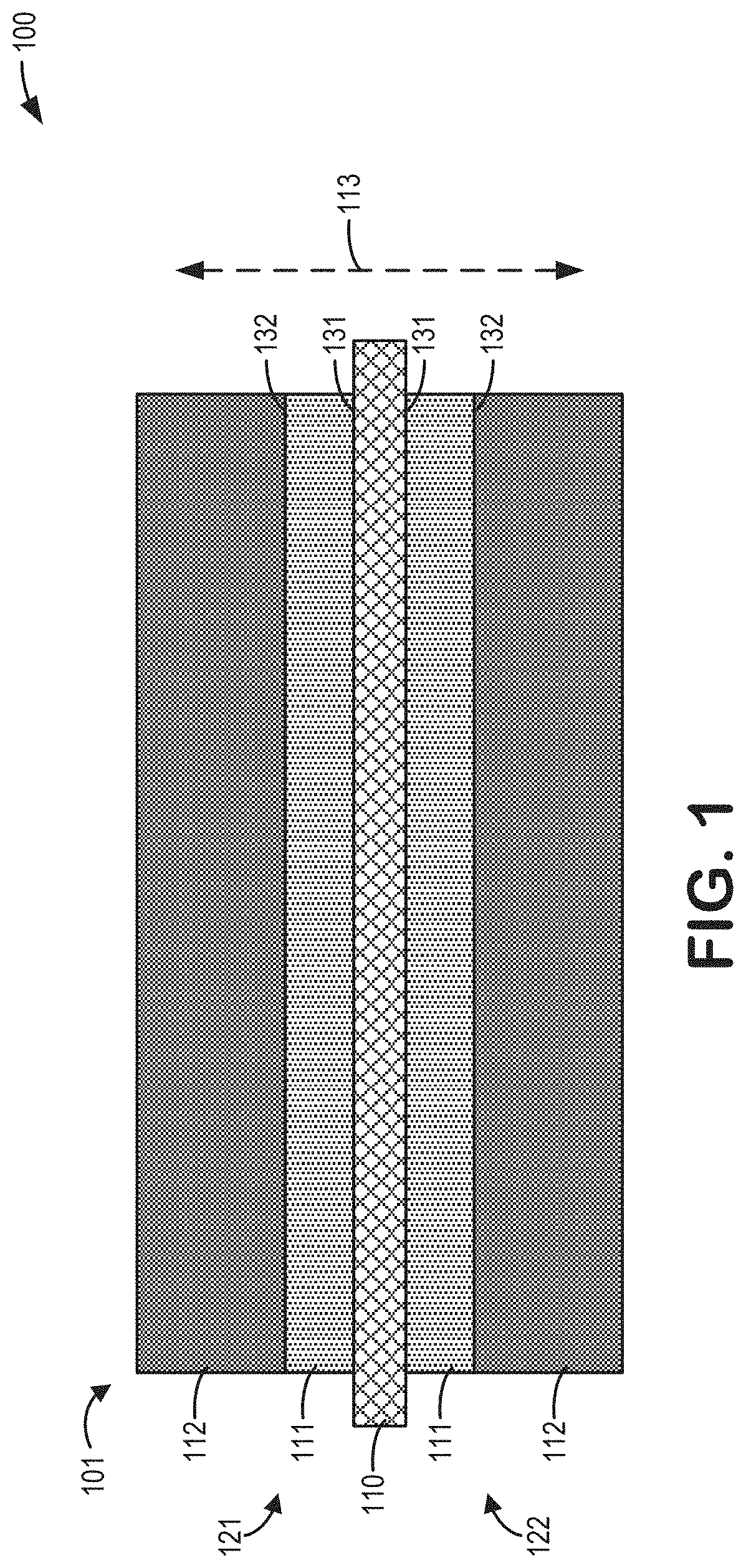
[0020]The following description relates to systems and methods for a multi-layered coated electrode for a lithium-ion secondary battery. The multi-layered coated electrode may include a current collector having one or more coating layers disposed thereon, such that the one or more coating layers may form a sequentially-layered configuration with respect to the current collector.

[0021]In one example, a first coating layer may be disposed on a surface of the current collector, and a second coating layer may be disposed on the first coating layer opposite to the current collector, such that the first coating layer may be interposed between the second coating layer and the current collector. In some examples, a “wet-on-wet” coating technique may be applied wherein the first coating layer and the second coating layer may be respectively disposed onto the current collector and the first coating layer prior to drying of either coating layer.

[0022]The first coating layer and second coating ...


PUM

PropertyMeasurementUnit
calendering densityaaaaaaaaaa
densityaaaaaaaaaa

Abstract

Systems and methods are provided for an electrode for a lithium-ion battery cell. In one example, the electrode may include a current collector having two opposing sides, at least one of the two opposing sides being configured with a first coating layer disposed on the current collector at a first loading, where the first coating layer may include a first binder in a first weight ratio, and a second coating layer disposed on the first coating layer at a second loading, where the second coating layer may include a second binder in a second weight ratio, wherein the first weight ratio may be greater than the second weight ratio, and a ratio of the first loading to the second loading may be less than 1:2. In this way, direct current internal resistance of the lithium-ion battery cell may be decreased while maintaining or increasing adhesion within the electrode.

Description

CROSS REFERENCE TO RELATED APPLICATIONS[0001]The present application claims priority to U.S. Provisional Application No. 63 / 042,950, entitled “MULTI-LAYERED COATED ELECTRODE FOR LITHIUM-ION BATTERY,” and filed on Jun. 23, 2020. The entire contents of the above-identified application are hereby incorporated by reference for all purposes.FIELD[0002]The present description relates generally to a coated electrode for a lithium-ion battery cell, wherein the coated electrode includes multiple coating layers.BACKGROUND AND SUMMARY[0003]Lithium-ion (Li-ion) battery cells are being increasingly used in electric and hybrid-electric vehicles. Especially in fully electric vehicles, Li-ion battery cells with higher energy densities are sought after to increase a duration between recharging. Accordingly, structural and compositional features may be contemplated which maximize the energy density of a given Li-ion battery cell.[0004]For example, electrodes may be developed which maximize coating we...

Claims


Application Information

Patent Timeline
Patent Type & Authority Applications(United States)
IPC IPC(8): H01M4/66H01M4/04H01M4/62H01M4/505H01M4/525H01M10/0525
CPCH01M4/663H01M4/0404H01M10/0525H01M4/505H01M4/525H01M4/623H01M4/0435H01M2004/021H01M4/622H01M4/625H01M4/131H01M4/136H01M4/1391H01M4/1397Y02E60/10
Inventor KIM, TAE KYOUNGWANG, JUNWILKINS, RONNIERUBIO, JORDANFAULKNER, ANKITALE, ZAIYUANWANG, XIQINGHUANG, TING
Owner A123 SYSTEMS LLC
Learn More