
A permanent magnet generator

Pending Publication Date: 2021-12-16
SAFRAN ELECTRICAL & POWER
View PDF0 Cites 0 Cited by
  • Summary
  • Abstract
  • Description
  • Claims
  • Application Information

AI Technical Summary

Benefits of technology

The invention is a generator used in aircraft engines that is designed to be fault-tolerant and has a high tolerance to unbalanced loads. The generator has a stator with double layer winding arrangements, which allows for independent operation of different power channels. This reduces the power loss during a fault in one channel and ensures that the other channels continue to deliver sufficient power. The generator also includes a rotor with a specially adapted permanent magnet to minimize eddy-current losses, which are often caused by fault conditions. The permanent magnet may be segmented or have a split phase belt to further reduce eddy-current losses. Overall, the invention provides a high-speed and reliable generator that is tolerant to faults and can still operate efficiently under unbalanced loads.

Problems solved by technology

However, unlike synchronous generators that use rotor windings to generate the rotor's magnetic field, a problem associated with permanent magnet generators is that the rotor flux is fixed and cannot be disabled.
However, such arrangements are limited by the fact that the electrical frequency is dictated by the number of poles.
For aerospace applications, the use of concentrated windings results in a high pole number, typically of 10 or more, which results in a very high electrical frequency at high speeds.
However, such frequencies are not manageable, or are at least very challenging, with current electronic control technologies, and such designs are therefore limited to uses that require speeds below 20000 rpm, in order to keep the electrical frequency and related losses within acceptable levels.
As such, the solution provided by concentrated windings is not suitable for high speed generators.
However, in such an arrangement, if the first set of windings is loaded and a short circuit happens on the second set of windings, then the first set of windings will experience a subsequent drop in voltage and power.
For example, in a dual three phase winding with a 30 degree electric shift, a three phase short circuit in one set of windings can result in a voltage and power drop in the other set of windings by almost 50%.
As such, standard distributed windings typically used for high speed generators do not provide fault tolerance.

Method used


Image

  • A permanent magnet generator
  • A permanent magnet generator
  • A permanent magnet generator

Examples


Embodiment Construction

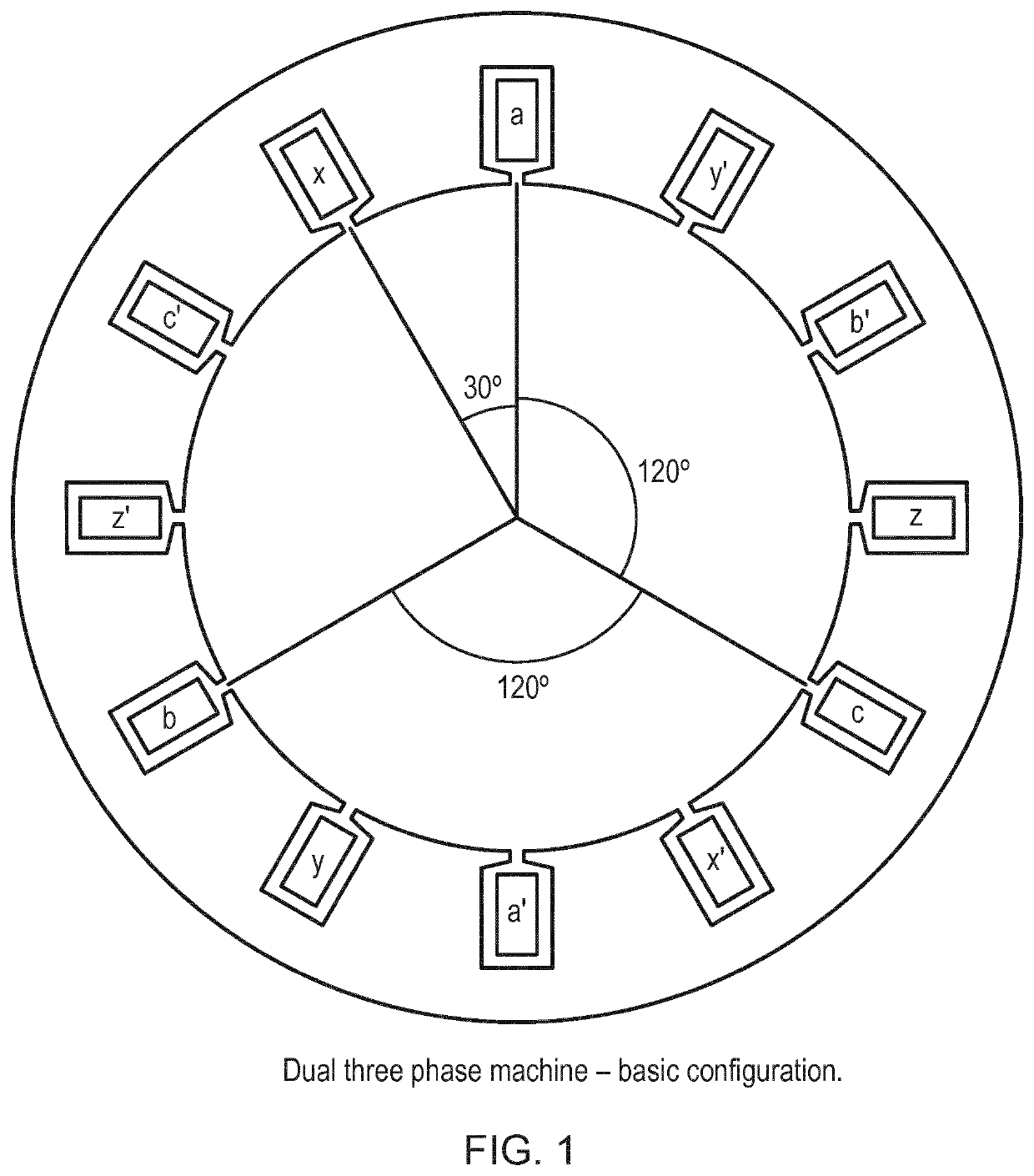
[0046]In order to achieve high speeds at lower electrical frequencies, one effective solution is to use at least two power channels, for example, by using two sets of windings with an electrical shift therebetween. An example of such an arrangement is shown in FIG. 1, which shows an example of a six phase machine with a 30 degree shift. Specifically, FIG. 1 shows a stator having a dual three phase arrangement with an electrical shift of 30°. The windings for each phase are split into two to provide two sets of electrically insulated windings, that is, two power channels, the first set of windings being denoted by a, b, c, a′, b′ and c′, and the second set of windings being denoted by x, y, z, x′, y′ and z′.

[0047]However, such an arrangement is not fault tolerant. If the first set of windings is loaded and a short circuit happens on the second set of windings, the power drops in the ‘healthy’, i.e. fault-free, first set of windings, which in turn results in a drop in output voltage f...


PUM


Abstract

A generator arranged to be driven by an aircraft engine, the generator comprising a stator and a rotor. The stator comprises a stator core and a plurality of slots longitudinally extending in a direction of a longitudinal axis of the stator, for receiving conductors to form windings of the stator, and a plurality of power channels. Each power channel comprises a set of windings having at least a first phase winding including a first set of coils comprising a plurality of conductors wound in a lap winding configuration, the first set of coils having a split phase belt such that the first set of coils comprises at least a first coil and a second coil, the first coil being mechanically shifted with respect to the second coil by a predetermined number of slots of the stator. The rotor comprises a permanent magnet adapted to reduce eddy-current losses.

Description

[0001]The present invention relates to a permanent magnet generator arranged to be driven by an aircraft engine. In particular, the invention relates to a high speed permanent magnet generator that is fault tolerant.BACKGROUND TO THE INVENTION[0002]Aircraft propulsion systems typically comprise an engine, such as a turbine or jet engine, which may be connected to an electrical generator. The electrical generator is typically formed of an assembly of magnetic circuit components, comprising a rotor and a stator. As is well known, rotation of the rotor relative to the stator causes interaction of the magnetic field generated by the rotor with windings provided on the stator, generating an induced electromotive force (EMF) and / or electrical current. In a permanent magnet generator, the rotor's magnetic field is produced by permanent magnets, which induces an AC voltage in the stator windings as the stator windings pass through the moving magnetic field of the permanent magnet.[0003]Many...

Claims


Application Information

Patent Timeline
IPC IPC(8): H02K21/04H02K3/28H02K1/17H02K1/27H02K21/48
CPCH02K21/04H02K3/28H02K1/17B60L50/10H02K21/48B60L2200/10H02K1/27H02K3/12H02K1/278H02K7/1823H02K2213/06H02K1/272H02K21/12H02K21/14
Inventor SOLER, JOSÉBOUBAKER, NADHEM
Owner SAFRAN ELECTRICAL & POWER
Learn More