
Riveting apparatus for thin heat sink fin and thin cover plate

a technology of heat sink fin and sinking structure, which is applied in the direction of manufacturing tools, lighting and heating apparatus, forging presses, etc., can solve the problems of more technical defects, inefficient and laborious, and defective products, so as to improve assembly efficiency, reduce product defects, and overall product thin and flat

Pending Publication Date: 2021-12-16
DONG GUAN HAN XU HARDWARE & PLASTIC TECH CO LTD
View PDF0 Cites 0 Cited by
  • Summary
  • Abstract
  • Description
  • Claims
  • Application Information

AI Technical Summary

Benefits of technology

The present invention provides a riveting structure for a thin heat sink fin and a thin cover plate, which improves assembly efficiency and reduces product defects. The raised portion on the heat sink fin is pressed and deformed by the rolling device to fill the space in the cover plate riveting hole, resulting in a structurally stable and thin flat product. This riveting method is suitable for a thin design and reduces the weight of the product, labor cost, and defect rate.

Problems solved by technology

This assembly is inefficient and labor intensive, and the thin cover plate is easily damaged by welding, resulting in defective products.
In this way, there will be more technical defects.
On the one hand, because the pins are hasped on the surface of the perforated plate after the pins are bent, the fit between the pins and the pin holes is often loose.
The pins hasped on the perforated plate will increase the overall thickness of the product (that is, the upper surface of the perforated plate increases the thickness of each pin), which is not suitable for a “thin” design.
The bent pins each have a barb shape, which is very inconvenient for installation.
At this time, the perforated plate is equivalent to directly bear the pressure of the roller, and the upper surface of the perforated plate is easily deformed after being pressed, and the fins may be broken.
Therefore, it is required to increase the thickness of the perforated plate to prevent deformation, which obviously does not conform to the current development trend of light, thin, short, and small products.

Method used


Image

  • Riveting apparatus for thin heat sink fin and thin cover plate
  • Riveting apparatus for thin heat sink fin and thin cover plate
  • Riveting apparatus for thin heat sink fin and thin cover plate

Examples


Embodiment Construction

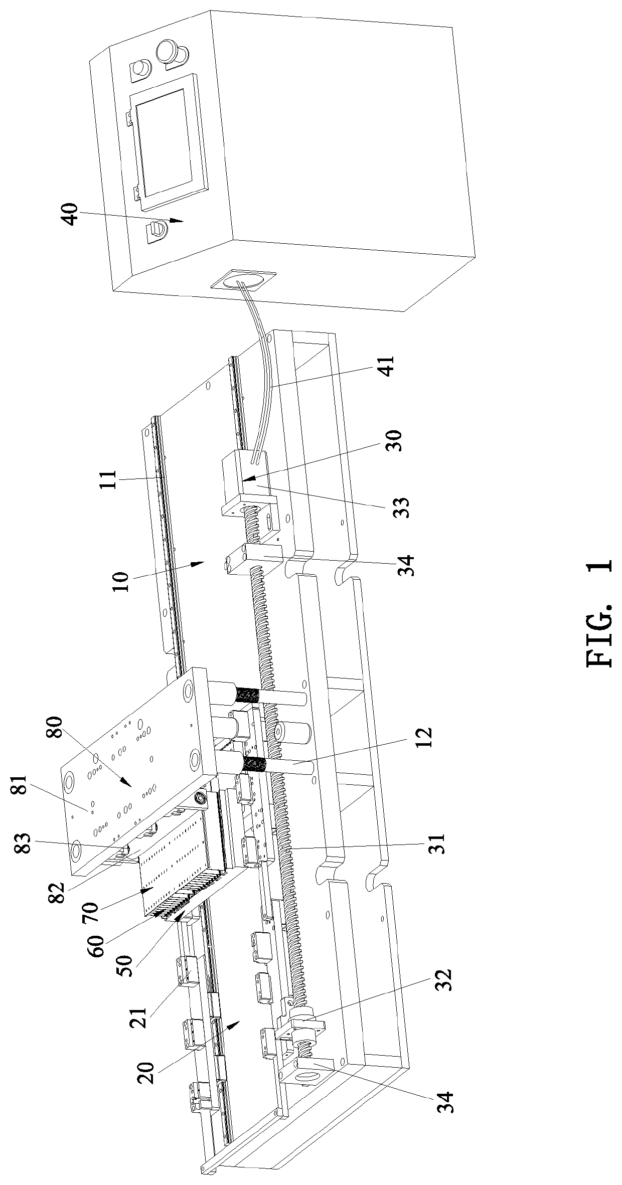
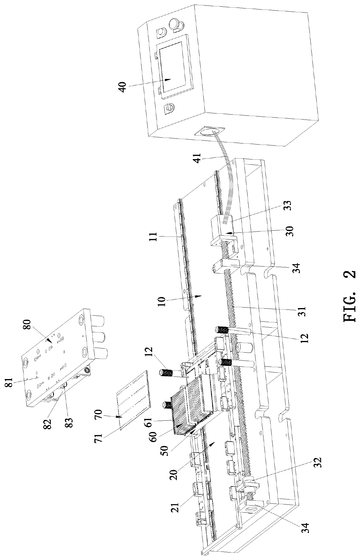
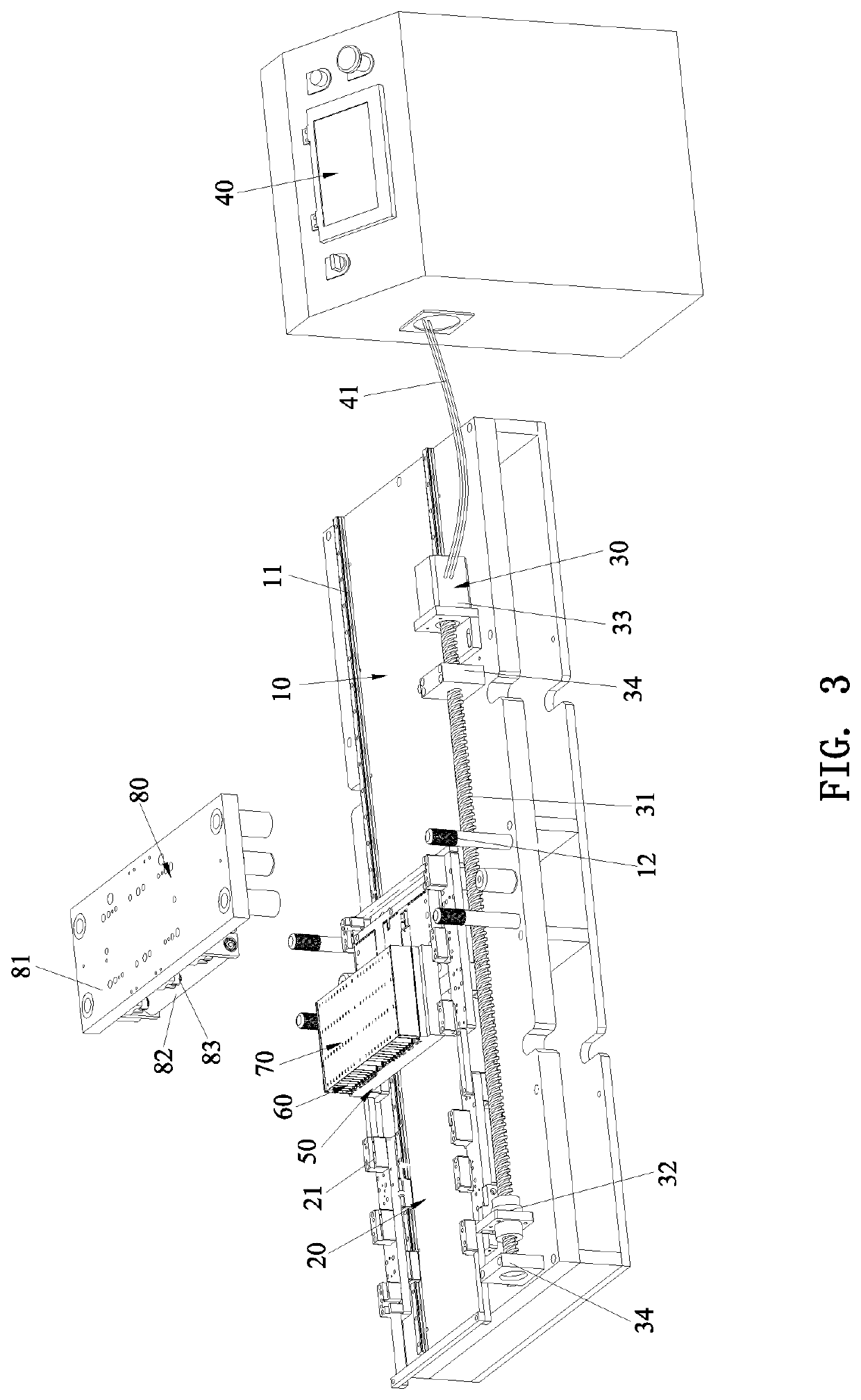
[0031]Referring to FIG. 1 through FIG. 4, a riveting apparatus for a thin heat sink fin and a thin cover plate according to a preferred embodiment of the present invention comprises a worktable 10, a feed frame 20, a driving device 30, and a control box 40.

[0032]The feed frame 20 is movably disposed on the worktable 10 to move back and forth transversely. The feed frame 20 is configured to carry a heat sink base 50. A plurality of thin heat sink fins 60 are vertically disposed on the heat sink base 50. The plurality of thin heat sink fins 60 are covered with a thin cover plate 70. The thin cover plate 70 is formed with a plurality of cover plate riveting holes 71. The top of each thin heat sink fin 60 is provided with a plurality of evenly spaced raised portions 61. The raised portion61 of each thin heat sink fin 60 passes through a corresponding one of the cover plate riveting holes 71 to extend upward. The cover plate riveting holes 71 each have a square shape. In this embodiment,...


PUM

PropertyMeasurementUnit
Volumeaaaaaaaaaa
Shapeaaaaaaaaaa
Efficiencyaaaaaaaaaa

Abstract

A riveting structure for a thin heat sink fin and a thin cover plate is disclosed. The riveting structure includes a plurality of thin heat sink fins and a thin cover plate. The top of each thin heat sink fin is provided with a raised portion, the thin cover plate is formed with a plurality of cover plate riveting holes, and the raised portion is pressed and deformed by a rolling device in a rolling manner to fill the space of a corresponding one of the cover plate riveting holes, thereby fixing the raised portion. It is suitable for a “thin” design, improves the assembly efficiency greatly, reduces the labor cost, and reduces the product defect rate effectively.

Description

CROSS REFERENCE TO RELAYED APPLICATIONS[0001]This is a continuation-in-part application of co-pending U.S. patent application Ser. No. 16 / 698,952, “RIVETING APPARATUS FOR THIN HEAT SINK FIN AND THIN COVER PLATE”, filed on Nov. 28, 2019.BACKGROUND OF THE INVENTION1. Field of the Invention[0002]The present invention relates to an apparatus for manufacturing a heat sink, and more particularly to a riveting structure for a thin heat sink fin and a thin cover plate.2. Description of the Prior Art[0003]A heat sink usually includes a heat sink base and heat sink fins disposed on the heat sink base. In order to improve the heat dissipation effect, a conventional heat sink generally adopts thin heat sink fins. Since a single thin heat sink fin is weak and easily deformed, a thin cover plate is mounted on the plurality of thin heat sink fins to enhance the overall strength of the heat sink. In the prior art, the thin cover plate is assembled to the heat sink fins by manual welding. This assem...

Claims


Application Information

Patent Timeline
IPC IPC(8): F28F3/06B21D39/03
CPCF28F3/06B21D39/031H01L21/4882H01L23/3672B21D53/04B21D39/032B21D39/038B21K25/00B21J5/08B21J9/025B21J15/12F16B17/008F16B5/045
Inventor HUANG, TSUNG-HSIEN
Owner DONG GUAN HAN XU HARDWARE & PLASTIC TECH CO LTD
Learn More