
Coaxial beverage keg connector comprising a ball joint

a technology ball joint, which is applied in the field of beverage keg connector comprising a ball joint, can solve the problems of high cost and heavy coaxial cabling, difficult to achieve, and difficult to achieve the effect of reducing the cost of coaxial cabling

Pending Publication Date: 2021-12-16
JOHN GUEST INT LTD
View PDF0 Cites 2 Cited by
  • Summary
  • Abstract
  • Description
  • Claims
  • Application Information

AI Technical Summary

Benefits of technology

The patent describes a system for improving the reception of vehicle antennas by using data network cabling instead of RF coaxial cable. This reduces the cost and weight of the wiring harness and ensures signal integrity. The antennas are hidden from view in the spoiler and can be effectively pointed downwards to compensate for signal attenuation. The system also avoids the need for expensive and heavy RF coaxial cable. The technical effects of this patent are improved signal quality, reduced cost and weight of the wiring harness, and improved efficiency of the antenna system.

Problems solved by technology

The inventors have recognised that the use of coaxial cabling to conventionally provide antenna signals to a radio unit is problematic because of the signal attenuation associated with such cables.
This is a particular issue with high frequency signals such as those used in modern cellular communications where dielectric attenuation and power loss can be significant.
Further, coaxial cabling is expensive and heavy which adds to the manufacturing costs and adds unwanted weight to the vehicle cable harness.
Also, having antennas located in so-called shark fin shaped enclosures on the roof is inevitably detrimental to the aerodynamic performance of the vehicle.
Further, despite attempts to make such structures pleasing to the eye they are still detrimental to the appearance of the vehicle.
If the antennas are placed within the vehicle cabin then not only is the reception is compromised and the attenuation problem with coaxial cable is exacerbated, but the available headroom in the vehicle is also unacceptably reduced.

Method used


Image

  • Coaxial beverage keg connector comprising a ball joint
  • Coaxial beverage keg connector comprising a ball joint
  • Coaxial beverage keg connector comprising a ball joint

Examples


Embodiment Construction

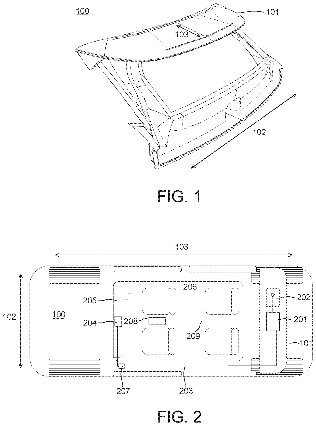
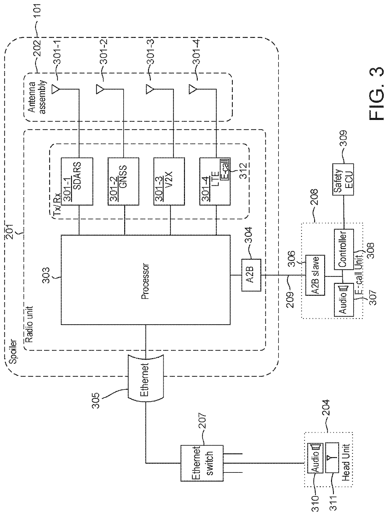
[0032]The vehicle 100 in FIG. 1 is a motor vehicle that includes a rear spoiler 101 mounted at the rear of the vehicle and extending from the roof of the vehicle to provide an aerodynamic surface substantially aligned with the roof of the vehicle to provide a continuous surface. A lateral axis 102 and a longitudinal axis 103 of the vehicle are indicated as shown and references to the lateral and longitudinal axes herewith are with respect to these axes of the vehicle. Although, a motor car is shown, the invention is applicable to other types of vehicle that may utilise a spoiler.

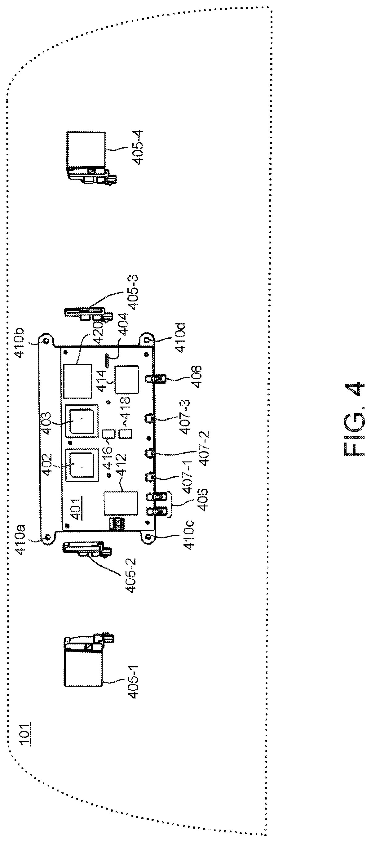
[0033]As shown in FIG. 2, a radio unit 201 and an antenna assembly 202 are located within the rear spoiler 101. The antenna assembly includes one or more antennas coupled to the radio unit 201 which includes respective receivers (receiving means) for demodulating signals received from the one or more antennas. Further, the radio unit 201 is configured so as to process the demodulated signals to provide an ou...


PUM


Abstract

An coaxial keg connector comprising a main body (1) made of plastic and having a first inlet port (3) and a second inlet port (3) receiving a stem (2). A coaxial outlet (10) comprises an outer outlet port (11) in communication with the first inlet port (3) and an inner outlet port (12) in communication with the second inlet port. The stem (2) comprises a tubular body with a main axis (31) with an inlet and a connector for attachment to the keg at one end. The second end of the stem opposite to the first end has an outlet in fluid communication with the inner outlet port (12) and comprises a ball joint (61) rotatably mounted in and sealed with respect to the main body (1) so as to be rotatable (12) about the main axis (31) of the tubular body and rotatable (67, 68) to a limited extent about axes perpendicular to the main axis.

Description

FIELD OF THE INVENTION[0001]The present invention relates to a spoiler assembly for a vehicle. Aspects of the invention also relate to a vehicle having a spoiler assembly.BACKGROUND OF THE INVENTION[0002]Motor vehicles increasingly require advanced data communication capabilities. Data throughput and signal integrity is thus of particular importance given the large amounts of data expected to be received and transmitted. For example, navigation, voice communication, multimedia and cellular data may all need to be received and / or transmitted by the vehicle systems. With this in mind conventional communication systems for motor vehicles typically use an antenna located on the roof of the vehicle and enclosed in a protective housing. The antenna is connected to a radio unit located about the cockpit of the vehicle via radio frequency (RF) coaxial cable. The radio unit contains the necessary electronics for demodulating and processing the RF signal received by the antenna and providing ...

Claims


Application Information

Patent Timeline
IPC IPC(8): B62D35/00H01Q1/32H04B1/3822H01Q9/04H01Q1/42H01Q5/307H01Q21/08
CPCB62D35/007H01Q1/3275H04B1/3822H01Q21/08H01Q1/42H01Q5/307H01Q9/0407B67D1/0829B67D1/0841B67D1/0857B67D2210/00062F16L27/042F16L37/0982F16L25/14F16L19/0231F16L19/025B67D1/0867
Inventor SMITH, JOSHUAANSELL, GLEN
Owner JOHN GUEST INT LTD
Learn More