Supporting assembly
a technology of supporting assembly and supporting rod, which is applied in the direction of casing/cabinet/drawer details, casing/cabinet/drawer details of electric apparatus, instruments, etc., can solve the problems of ineffective protection of in-vehicle computer or server from vibration damage, up and down vibrations to the vehicle, etc., so as to effectively mitigate the vibrations transferred to the casing of the electronic device.
- Summary
- Abstract
- Description
- Claims
- Application Information
AI Technical Summary
Benefits of technology
Problems solved by technology
Method used
Image
Examples
first embodiment
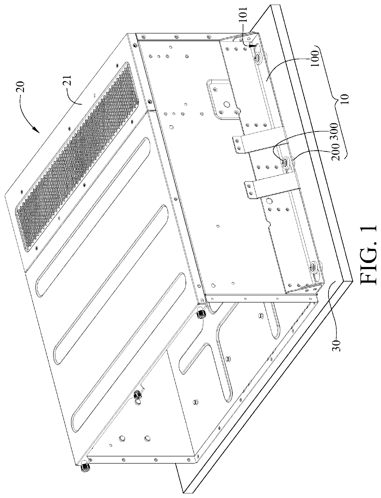
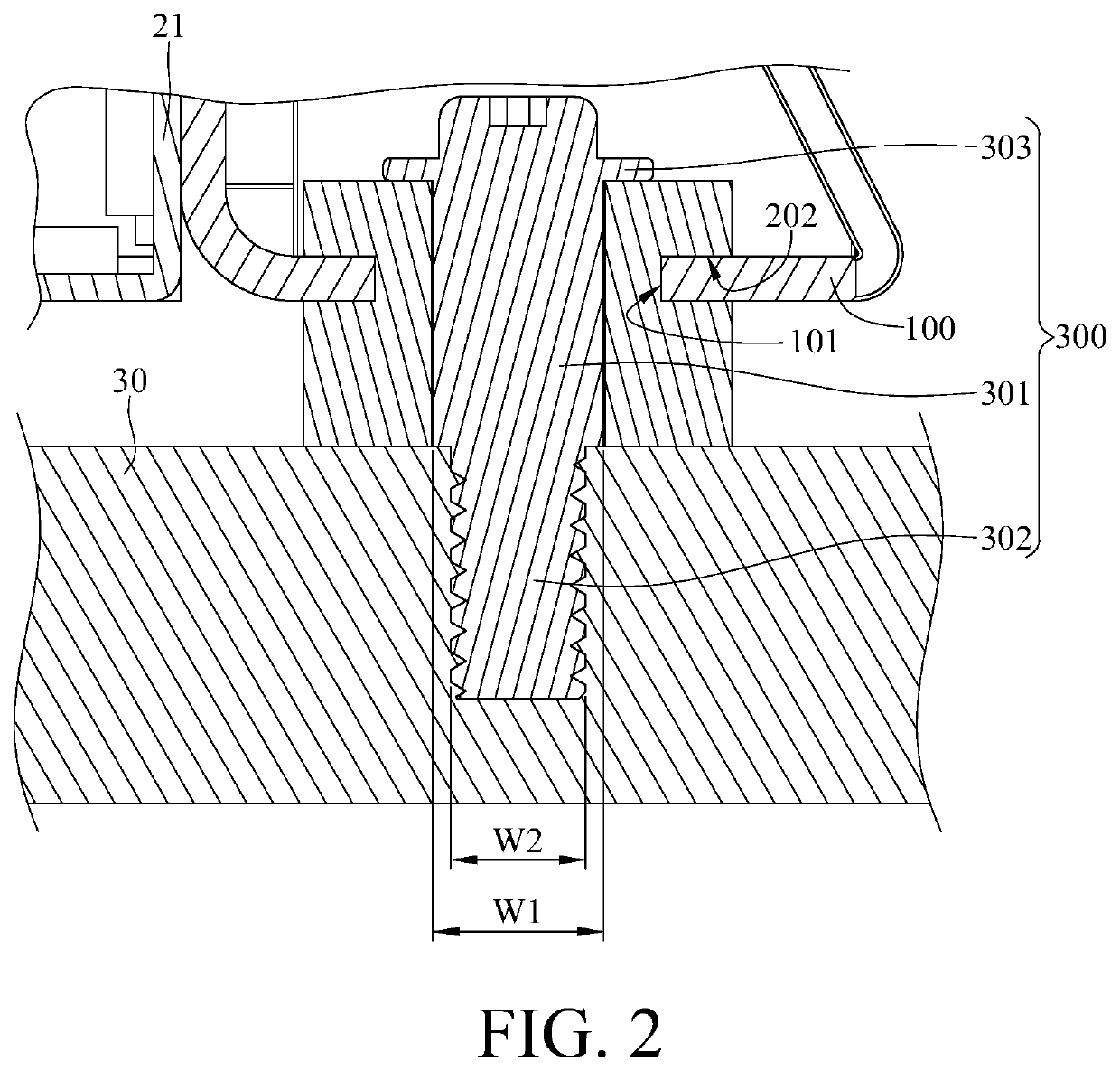
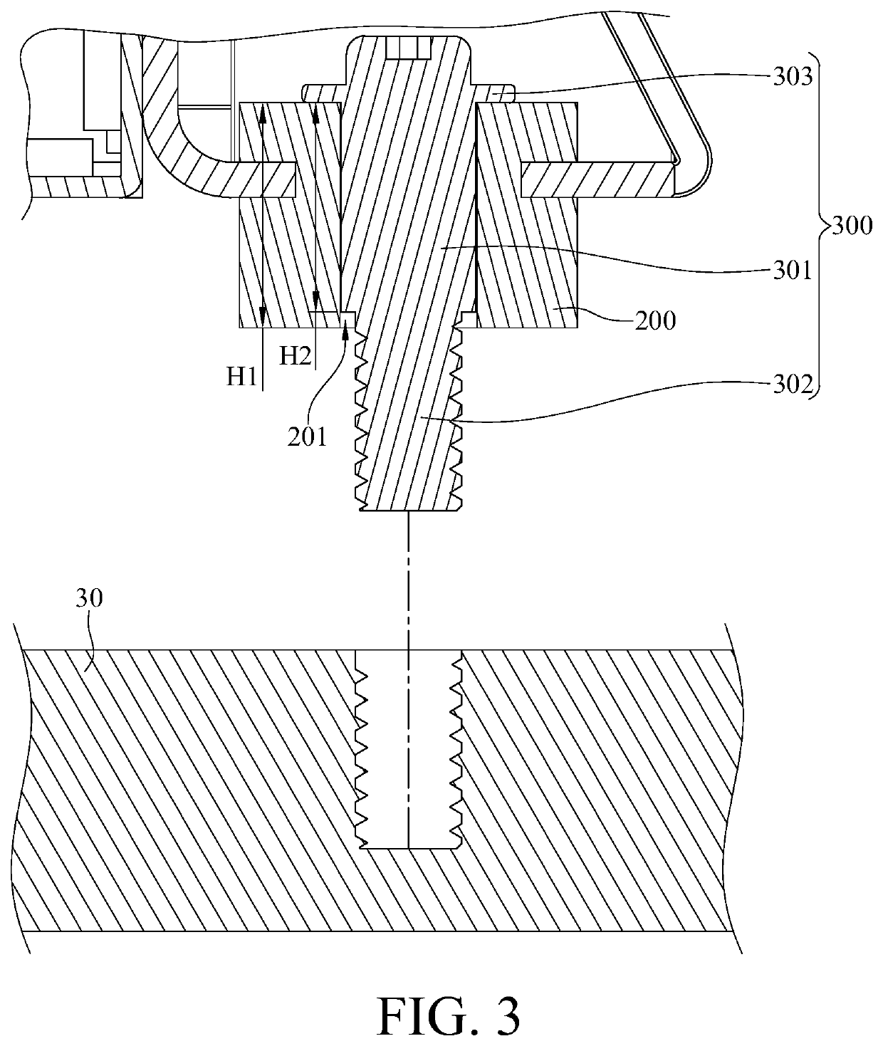
[0016]Please refer to FIG. 1 to FIG. 3, where FIG. 1 is a perspective view showing that a casing 21 of an electronic device 20 is mounted on a supporting assembly 10 according to the invention, FIG. 2 is a partially enlarged side cross-sectional view of the supporting assembly 10 and the casing 21 of the electronic device 20 in FIG. 1, and FIG. 3 is a side cross-sectional view showing that a cushioning component 200 of the supporting assembly 10 in FIG. 2 is not deformed.
[0017]The supporting assembly 10 is configured to be mounted on a side of the casing 21 of the electronic device 20 so as to fix the casing 21 to a chassis 30; in other words, the supporting assembly 10 is configured for installing the electronic device 20 to the chassis 30. In this embodiment, the supporting assembly 10 includes a plate body 100, a plurality of cushioning components 200, and a plurality of fasteners 300. In this embodiment, the electronic device 20 is, for example, an automotive computer or an in-v...
second embodiment
[0026]Note that the above configuration of the cushioning component 200 and connection between the cushioning component 200 and the chassis 30 are exemplary and not intended to limit the invention. For example, please refer to FIG. 4 and FIG. 5, where FIG. 4 is a partially enlarged side cross-sectional view of a supporting assembly 10a and a casing 21a of an electronic device 20a, and FIG. 5 is a side cross-sectional view showing that a cushioning component 200a of the supporting assembly 10a in FIG. 4 is not deformed.
[0027]In this embodiment, the supporting assembly 10a includes a plate body 100a, the cushioning component 200a, a positioning pillar 400a and a fastener 300a. The plate body 100a includes a mounting hole 101a and is configured to be fixed to the casing 21a of the electronic device 20a.
[0028]In this embodiment, the cushioning component 200a is a two-piece structure. In detail, the cushioning component 200a includes a first cushioning component 210a and a second cushi...
PUM
 Abstract
Description
Claims
Application Information
 - R&D
- Intellectual Property
- Life Sciences
- Materials
- Tech Scout
- Unparalleled Data Quality
- Higher Quality Content
- 60% Fewer Hallucinations
Browse by: Latest US Patents, China's latest patents, Technical Efficacy Thesaurus, Application Domain, Technology Topic, Popular Technical Reports.
© 2025 PatSnap. All rights reserved.Legal|Privacy policy|Modern Slavery Act Transparency Statement|Sitemap|About US| Contact US: help@patsnap.com


