Fuse link comprising permanent magnet for inducing arc directivity

Inactive Publication Date: 2021-11-18
HONG SEUNG PYO
View PDF0 Cites 0 Cited by
  • Summary
  • Abstract
  • Description
  • Claims
  • Application Information

AI Technical Summary

Benefits of technology

The present invention reduces the size of fuse links by reducing the blocking speed and current of fuse links, which improves safety and reduces the size of protective fuse links. The size of the system using fuse links is also reduced, which solves space limitations. The blocking speed is increased, and the blocking time is reduced, which reduces the amount of arc energy generated and the peak value of arc blocking current. The cost of manufacturing fuse links is also reduced.

Problems solved by technology

Therefore, the direction and uniformity of the arc energy cannot be guaranteed.
As a result, there is a problem that the fuse explodes when a fault current, which is a large current, occurs because the melting rate of the element notched portion is slow.
However, if the magnetic field intensity is largely introduced only to the notched portion at a specific point, simultaneous melting of the notched portion becomes impossible.
Due to this, the fuse explodes due to the fault current or causes a fire, causing a fatal problem that cannot protect the circuit.

Method used


Image

  • Fuse link comprising permanent magnet for inducing arc directivity
  • Fuse link comprising permanent magnet for inducing arc directivity
  • Fuse link comprising permanent magnet for inducing arc directivity

Examples


first embodiment

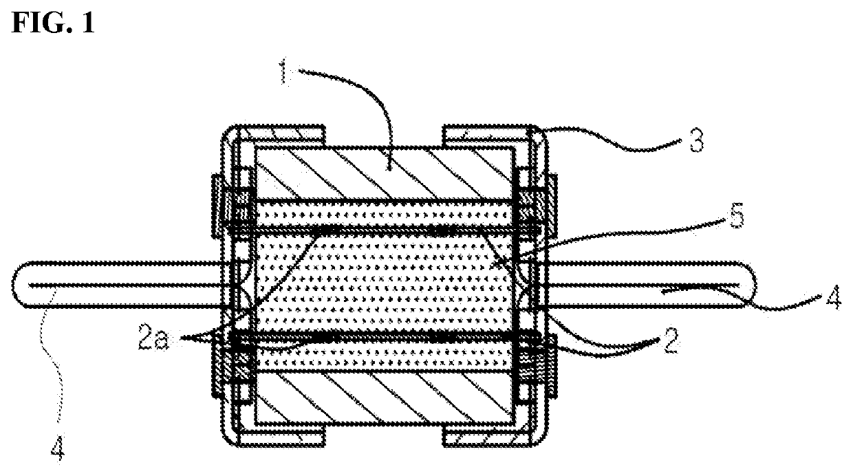
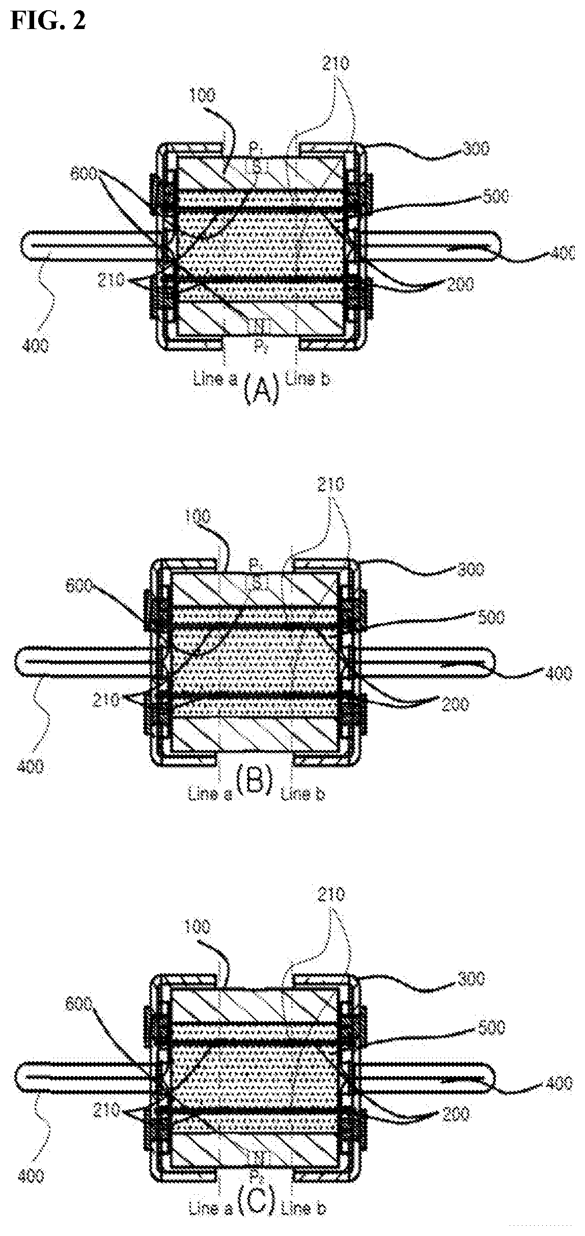
[0058]First, according to the magnet arrangement of the present invention shown in FIG. 2, in the magnet 600, at least one magnet is disposed in an insulating tube at a position corresponding to a middle point between the notched portion and the notched portion (P1, P2 in FIG. 2), so that the magnetic field intensity of the same size is induced in each notched portion 210.

[0059]At least one or more magnet disposed in an insulating tube at a position (P1, P2 in FIG. 2) corresponding to a middle point between the notched portion 210 and the notched portion 210, as shown in FIG. 2(A), may be disposed in both at the insulating tube (the outer surface or the inner surface or inside of the insulating tube) of the vertical upper point of the element (P1 in FIG. 2) corresponding to the middle point between the notched portion and the notched portion and the insulating tube (the outer surface or the inner surface or inside of the insulating tube) of the vertical lower point of the element (P...

second embodiment

[0067]Next, according to the magnet arrangement of the present invention shown in FIG. 4, the magnet 600, at least one magnet is a position (P1 in FIG. 4) corresponding to the middle point between the notched portion and the notched portion to induce the magnetic field intensity of the same size in each notched portion.

[0068]At least one or more magnet disposed in an insulating tube at a position (P1 in FIG. 4) corresponding to a middle point between the notched portion 210 and the notched portion 210, as shown in FIG. 5(A), may be disposed in both at the insulating tube (the outer surface or the inner surface or inside of the insulating tube) of one point horizontal in the lateral direction of the element corresponding to the middle point between the notched portion and the notched portion and at the insulating tube (the outer surface or the inner surface or inside of the insulating tube) of other point horizontal in the lateral direction of the element corresponding to the middle ...

third embodiment

[0072]Next, according to the magnet arrangement of the present invention shown in FIG. 6, in the magnet 600, at least two or more magnet is disposed in an insulating tube at a position (P1, P2 in FIG. 6) corresponding to the notched portion, so that the magnetic field intensity of the same size is induced in each notched portion.

[0073]At least two or more magnet disposed in an insulating tube at a position (P1, P2 in FIG. 6) corresponding to the notched portion, as shown in FIG. 6(A), may be disposed in both at the insulating tube (the outer surface or the inner surface or inside of the insulating tube) of the vertical upper point (P1 in FIG. 6) of the element corresponding to notched portion and the insulating tube (the outer surface or the inner surface or inside of the insulating tube) of the vertical lower point (P2 in FIG. 6) of the element corresponding to the notched portion, or as shown in FIG. 6(B), may be disposed only at the insulating tube (the outer surface or the inner...


PUM


Abstract

A fuse link including magnet for inducing arc directivity is provided, in which the magnet is arranged in an inner surface, an outer surface or the inside of an insulating tube forming the fuse link, and the progress direction of arc energy is coherently directed in a certain direction in accordance with Fleming's left-hand rule by the direction of magnetic field of the arranged magnet so as to increase a disconnection speed of an element (i.e., reducing a blocking speed of a fault current), thereby increasing fault current blocking performance of the fuse link. In particular, a position of the magnet arranged on the insulating tube is arranged at a middle point between a notched portion and the notched portion, a point of notched portion, and the insulating tube corresponding to the middle point between the notched portion and the notched portion and the point of notched portion.

Description

TECHNICAL FIELD[0001]The present invention relates to a fuse link that is installed in a power distribution device or the like to block current when a fault current occurs. A fuse assembly is mounted on the power line for the purpose of protecting the load from fault currents in the event of fault current such as short circuit / ground fault / over current for AC / DC power supply. The fuse assembly includes a fuse base that houses the fuse therein and a fuse that is housed inside the fuse link. Depending on the type of these fuses, protection functions are added according to functional classifications such as short circuit protection and over current / short circuit protection. The fuse is intended to prevent fire and protect human life by disconnecting the power current by melting and blocking the element inside the fuse to protect the load from a fault current when the fault current flows in. When a fault current flows into the fuse, a current disconnection occurs due to the melting of t...

Claims


Application Information

Patent Timeline
IPC IPC(8): H01H85/02H01H85/38H02B1/18
CPCH01H85/0241H01H2085/386H02B1/18H01H85/38H01H85/10H01H9/443
Inventor HONG, SEUNG PYO
Owner HONG SEUNG PYO
Why Eureka
Try Eureka