Micromechanical component for a sensor or microphone device

a micromechanical and microphone technology, applied in microelectromechanical systems, electrical apparatus, electromechanical/electrostrictive/magnetostrictive devices, etc., can solve the problem of mechanical limitation of the maximum warping of the diaphragm, and achieve the effect of comparatively easy manufacturing and cost-effectiveness

Pending Publication Date: 2021-11-18
ROBERT BOSCH GMBH
View PDF0 Cites 0 Cited by
  • Summary
  • Abstract
  • Description
  • Claims
  • Application Information

AI Technical Summary

Benefits of technology

[0012]In one further advantageous specific embodiment of the micromechanical component, the bending beam structure and at least one reference electrode, attached at the frame structure, at the substrate surface and / or at the at least one intermediate layer, and / or at least one measuring electrode are formed of a first semiconductor and / or metal layer, and / or the diaphragm, the at least one coupling structure and / or at least one suspension structure via which the at least one measuring electrode is suspended at the diaphragm inner side is / are formed of a second semiconductor and / or metal layer. The micromechanical component described here may thus be manufactured comparatively easily and cost-effectively, despite it being equipped with at least one reference electrode and / or at least one measuring electrode.
[0013]Furthermore, an execution of a corresponding manufacturing method for a micromechanical component for a sensor or microphone device also provides the above-described advantages, it being possible for the manufacturing method to be refined according to the above-explained specific embodiments of the micromechanical component.

Problems solved by technology

With the aid of the at least one stop structure, a maximum warping of the diaphragm may be mechanically limited.

Method used


Image

  • Micromechanical component for a sensor or microphone device
  • Micromechanical component for a sensor or microphone device
  • Micromechanical component for a sensor or microphone device

Examples


Embodiment Construction

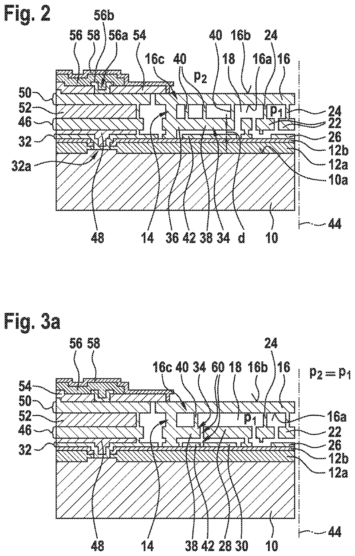
[0025]FIG. 2 shows a schematic partial representation of a first specific embodiment of the micromechanical component in accordance with the present invention.

[0026]The micromechanical component partially shown schematically in FIG. 2 has a substrate 10 including a substrate surface 10a which, for example, is a semiconductor substrate, in particular, a silicon substrate. Substrate surface 10a is at least partially covered by at least one intermediate layer 12a and 12b. The at least one intermediate layer 12a and 12b may, for example, be at least one insulating layer 12a and 12b, such as, in particular, a silicon dioxide layer 12a and / or a silicon-rich silicon nitride layer 12b. Optionally, a strip conductor layer 32 may be deposited on substrate surface 10a and / or the at least one intermediate layer / insulating layer 12a and 12b, an electrical contact 32a being formable / formed in each case, for example, by way of a direct contact between substrate surface 10a and strip conductor laye...


PUM


Abstract

A micromechanical component for a sensor or microphone device, including a substrate, a frame structure, which is situated on the substrate surface and/or at least one intermediate layer, and a diaphragm, which spans an inner volume, which is at least partially framed by the frame structure. The micromechanical component includes a bending beam structure, which is situated in the inner volume and includes at least one anchoring area, which is attached to the frame structure, to the substrate surface and/or to the at least one intermediate layer, and at least one self-supporting area, which is connected via at least one coupling structure to the diaphragm inner side of the diaphragm in such a way that the at least one self-supporting area is bendable by way of a warping of the diaphragm.

Description

CROSS REFERENCE[0001]The present application claims the benefit under 35 U.S.C. § 119 of German Patent Application No. DE 102020206242.0 filed on May 18, 2020, which is expressly incorporated herein by reference in its entirety.FIELD[0002]The present invention relates to a micromechanical component for a sensor or microphone device. The present invention furthermore relates to a manufacturing method for a micromechanical component for a sensor or microphone device.BACKGROUND INFORMATION[0003]FIG. 1 shows a schematic representation of a conventional pressure sensor device which is internal related art to the applicant.[0004]The pressure sensor device schematically represented in FIG. 1 includes a substrate 10 including a substrate surface 10a, a frame structure 14, which is situated on at least one intermediate layer 12a and 12b at least partially covering substrate surface 10a, and a diaphragm 16. Diaphragm 16 spans an inner volume 18, which is at least partially framed by frame str...

Claims


Application Information

Patent Timeline
Patent Type & Authority Applications(United States)
IPC IPC(8): B81B3/00
CPCB81B3/0056B81B2201/0264B81B2201/0257B81B2203/0315B81B2203/019B81B2203/0307B81B2203/0127B81B7/02B81B7/0009B81B2201/02B81B7/0016B81B2203/0109
Inventor WEBER, HERIBERTSCHEURLE, ANDREASFRITZ, JOACHIMSCHMOLLNGRUBER, PETERMACH, SOPHIELOUISEFRIEDRICH, THOMAS
Owner ROBERT BOSCH GMBH
Why Eureka
Try Eureka