
Power Supply System and Vibrating Processing Apparatus

a power supply system and processing device technology, applied in the direction of instruments, device details, piezoelectric/electrostrictive device details, etc., can solve the problems of unstable vibrator, limited operation and mechanical design of spindle and processing tool, and resonance frequency of primary coil, secondary coil, etc., to achieve the effect of increasing design flexibility and mitigating the limitation of the distance between the primary coil and the secondary coil

Pending Publication Date: 2021-11-11
ACROW MACHINERY MFG
View PDF4 Cites 0 Cited by
  • Summary
  • Abstract
  • Description
  • Claims
  • Application Information

AI Technical Summary

Benefits of technology

The present invention aims to provide a power supply system for vibrating processing apparatus, which will be more flexible in design. This will reduce the limitation of the distance between the primary coil and the secondary coil.

Problems solved by technology

Thus, the operation and the mechanical design of the spindle and the processing tool are limited.
However, the resonance frequency of the primary coil, the secondary coil, and the vibrator is unstable because of the rotation of the spindle, the loading of processing, and the temperature.

Method used


Image

  • Power Supply System and Vibrating Processing Apparatus
  • Power Supply System and Vibrating Processing Apparatus
  • Power Supply System and Vibrating Processing Apparatus

Examples


Embodiment Construction

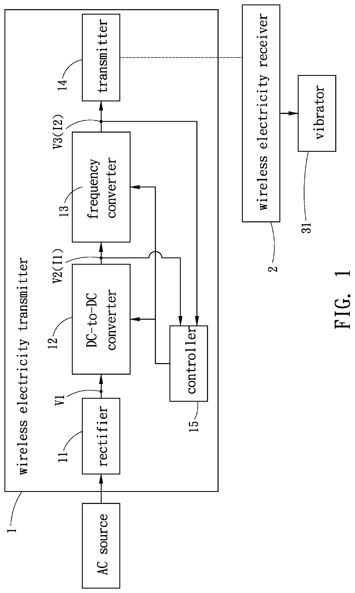
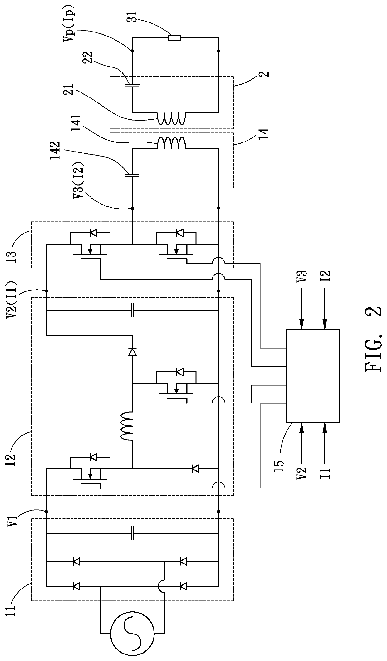
[0021]Please refer to FIG. 1 and FIG. 2, the present invention provides a power supply system adapted for being disposed on a vibrating processing apparatus to supply electricity to the vibrator therein. The vibrator has a resonance frequency. The power supply system includes a wireless electricity transmitter 1 and a wireless electricity receiver 2.

[0022]The wireless electricity transmitter 1 includes a rectifier 11, a DC-to-DC converter 12, a frequency converter 13, a transmitter 14, and a controller 15.

[0023]The rectifier 11 can be a bridge rectifier to receive AC input and to output DC V1.

[0024]The DC-to-DC converter 12 can be buck-boost converter and is connected to the rectifier 11 to be electrically triggered by the rectifier 11. In other possible embodiments, half-bridge converter, bridge converter, flyback converter, or other types of converter can be used as the DC-to-DC converter.

[0025]The frequency converter 13 can be an inverter and is connected to the DC-to-DC converte...


PUM


Abstract

The power supply system of the present invention includes a wireless electricity transmitter and a wireless electricity receiver transmitting electricity by electromagnetic coupling. The wireless electricity receiver is further connected to a vibrator of a vibrating processing apparatus to transmit electricity thereto. The wireless electricity transmitter has a controller to monitor the operating voltage and the operating current of the transmitter, and alternates the oscillation frequency of the operating voltage according to the phase difference between the operating voltage and the operating current. Thereby, the oscillation frequency may approach the resonance frequency of the vibrator in order to improve the efficiency of electricity transmission. Also, the distance between the wireless electricity transmitter and the wireless electricity receiver can be increased.

Description

FIELD OF THE INVENTION[0001]The present disclosure relates to a vibrating processing apparatus such as an ultrasonic processing tool, which is provided with electricity by the wireless electricity transmitter to vibrate to process.BACKGROUND OF THE INVENTION[0002]A vibrating processing apparatus cuts workpieces by its vibrating tool. It is advantageous in the processing of materials in high hardness, in high brittleness, or with flexibility, as disclosed in patents TW 1671159 and TW 1666087.[0003]In the patents mentioned above, in order to process by milling and vibrating, the processing tool is installed on a rotatable spindle, and the electricity is transmitted to the spindle or the processing tool by coil induction. To increase the efficiency of coil induction, the primary coil outside the spindle and the secondary coil on the spindle or the processing tool have to be arranged near each other. Practically, the distance between the primary coil and the secondary coil has to be sma...

Claims


Application Information

Patent Timeline
Patent Type & Authority Applications(United States)
IPC IPC(8): H02J50/12H02M3/155H01L41/09H01L41/04H10N30/20H10N30/80
CPCH02J50/12H01L41/042H01L41/09H02M3/155H02M3/1582H02M1/4208H02M1/0058H02M7/53803H02M7/4815H02M1/007Y02B70/10H10N30/20H10N30/802
Inventor LEE, CHAO-CHINGLAI, CHIA-HSINWU, YUNG-CHUN
Owner ACROW MACHINERY MFG
Learn More