
Quasi-reflectionless microstrip bandpass filters with improved passband flatness and out-of-band rejection

a bandpass filter and quasi-reflectionless technology, applied in the direction of transmission, electrical equipment, etc., can solve the problems of deteriorating the performance of adjacent non-linear devices, presenting significantly mismatched impedance to undesired (out-of-band) signals, and imposing a cost on the approach, so as to facilitate phase cancellation of signals

Active Publication Date: 2021-11-04
RGT UNIV OF CALIFORNIA
View PDF0 Cites 2 Cited by
  • Summary
  • Abstract
  • Description
  • Claims
  • Application Information

AI Technical Summary

Benefits of technology

The patent describes a filter that allows signals at certain frequencies to pass through while cancelling out other signals. This is achieved by using a cross-coupling connection between two absorptive stubs. The technical effect is improved signal quality within a specific band of frequencies.

Problems solved by technology

In a conventional filter, rejection is achieved by presenting significantly mismatched impedance to the undesired (out-of-band) signals.
In some systems, such reflection will deteriorate the performance of adjacent non-linear devices, such as analog-to-digital converters, mixers, and high-gain amplifiers.
However, this approach comes at a cost because the magnetic non-reciprocal devices are known to be bulky, expensive, bandwidth limited, and are difficult to integrate with the rest of the active electronics.
However, these proposed designs have a number of drawbacks, including: providing limited bandwidth; having a large circuit size; causing high insertion loss; and exhibiting absorptive behavior in only a limited frequency range.
As a consequence, reflectionless bandpass filters, particularly those that are well-matched at both the input and output ports, still remain a challenge to design.

Method used


Image

  • Quasi-reflectionless microstrip bandpass filters with improved passband flatness and out-of-band rejection
  • Quasi-reflectionless microstrip bandpass filters with improved passband flatness and out-of-band rejection
  • Quasi-reflectionless microstrip bandpass filters with improved passband flatness and out-of-band rejection

Examples


Embodiment Construction

[0048]The following description is presented to enable any person skilled in the art to make and use the present embodiments, and is provided in the context of a particular application and its requirements. Various modifications to the disclosed embodiments will be readily apparent to those skilled in the art, and the general principles defined herein may be applied to other embodiments and applications without departing from the spirit and scope of the present embodiments. Thus, the present embodiments are not limited to the embodiments shown, but are to be accorded the widest scope consistent with the principles and features disclosed herein.

[0049]The data structures and code described in this detailed description are typically stored on a computer-readable storage medium, which may be any device or medium that can store code and / or data for use by a computer system. The computer-readable storage medium includes, but is not limited to, volatile memory, non-volatile memory, magneti...


PUM


Abstract

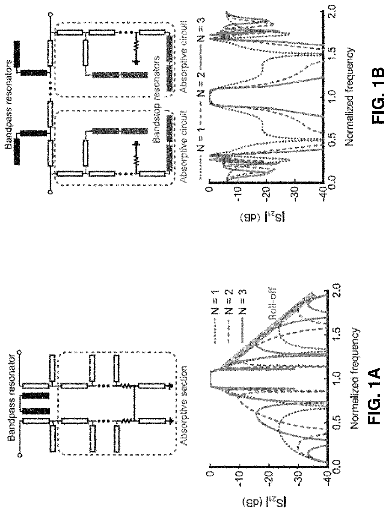
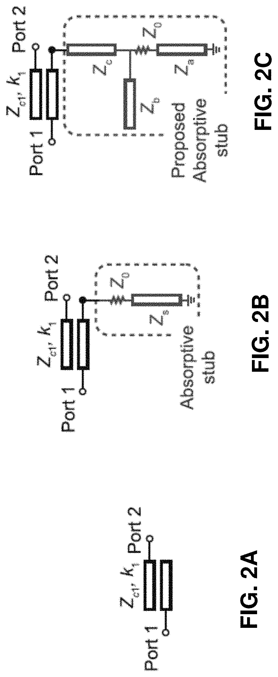
The disclosed embodiments provide an absorptive coupled-line bandpass filter. This bandpass filter includes a first port, which is coupled to a first absorptive stub, and a second port, which is coupled to a second absorptive stub. The bandpass filter also includes a coupled-line bandpass section coupled between the first and second ports, wherein the coupled-line bandpass section comprises a set of one or more parallel strip line resonators, which are coupled together in series and are coupled to the first and second ports through overlapping coupled-line sections, wherein at a center frequency of a passband for the absorptive coupled-line bandpass filter, the first and second absorptive stubs appear as open circuits, and outside of the passband, the first and second absorptive stubs appear as matched loads to ground and contribute to absorption of out-of-band signals.

Description

CROSS-REFERENCE TO RELATED APPLICATION[0001]This application claims the benefit of U.S. Provisional Patent Application Ser. No. 63 / 018,232, entitled “Absorptive Microstrip Bandpass Filters with Improved Passband Flatness and Out-of-Band Rejection,” by inventors Xiaoguang Liu and Xiaohu Wu, filed on 30 Apr. 2020, the contents of which are incorporated by reference herein.BACKGROUNDField[0002]The disclosed embodiments generally relate to the design of bandpass filters that function as building blocks in radio frequency (RF) and microwave systems. More specifically, the disclosed embodiments relate to the design of a quasi-reflectionless microstrip bandpass filter that provides improved passband flatness and out-of-band rejection.Related Art[0003]As fundamental building blocks in radio frequency (RF) and microwave systems, filters are used to better define the system bandwidth or reject undesired signals. In a conventional filter, rejection is achieved by presenting significantly misma...

Claims


Application Information

Patent Timeline
IPC IPC(8): H04B1/00H04B1/30H04B1/40
CPCH04B1/0057H04B1/001H04B2001/307H04B1/40H04B1/30
Inventor WU, XIAOHULIU, XIAOGUANG
Owner RGT UNIV OF CALIFORNIA
Learn More