
Treatment apparatus

a technology of treatment apparatus and needle insertion depth, which is applied in the field of skin treatment devices and methods, can solve the problems of affecting the delivery of rf energy, unable to have the requisite experience, and/or selecting the needle insertion depth and/or energy level improperly,

Pending Publication Date: 2021-11-04
CANDELA CORP
View PDF0 Cites 0 Cited by
  • Summary
  • Abstract
  • Description
  • Claims
  • Application Information

AI Technical Summary

Benefits of technology

This patent is related to a safety routine for a needle depth setter that limits the user's energy level options when a depth is set below a certain level. The default setting is set to 2 Joules of applied energy for subcutaneous or dermal areas to partially denature collagen and optimize the healing response. This ensures that even inexperienced users always receive the maximum effective energy levels without needing to change the default settings. The user interface of the device also displays a default energy per needle level of 0.0408 Joule for creating thermal injuries in the subcutaneous or dermal area to partially denature collagen.

Problems solved by technology

Some users, however, may lack the requisite experience and / or select needle insertion depths and / or energy levels improperly.
We have discovered, for example, that if the needles are inserted to a depth of 1.5 mm or less from the skin surface and an energy level of over 2 Joules is applied, the result, in some conditions, can be the creation of an undesirable thermal injury to the skin surface.
In other conditions, charring can result along the active portion of the needle and impede the delivery of RF energy.

Method used


Image

  • Treatment apparatus
  • Treatment apparatus
  • Treatment apparatus

Examples


Embodiment Construction

[0026]Aside from the preferred embodiment or embodiments disclosed below, this invention is capable of other embodiments and of being practiced or being carried out in various ways. Thus, it is to be understood that the invention is not limited in its application to the details of construction and the arrangements of components set forth in the following description or illustrated in the drawings. If only one embodiment is described herein, the claims hereof are not to be limited to that embodiment. Moreover, the claims hereof are not to be read restrictively unless them is clear and convincing evidence manifesting a certain exclusion, restriction, or disclaimer.

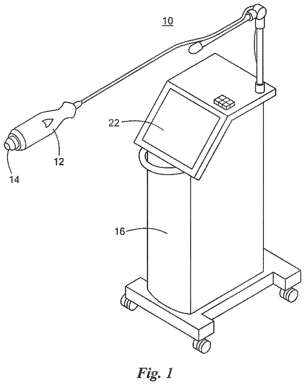
[0027]An exemplary treatment apparatus 10, FIG. 1 includes handpiece 12 with a plurality of needles 14, typically in an array, configured to provide radio frequency to energy to the patient's dermis. Console 16 preferably includes a source of radio frequency energy 18, FIG. 2 for supplying radio frequency energy to the plura...


PUM


Abstract

A treatment apparatus system includes a plurality of needles configured to provide radio frequency energy, a source of radio frequency energy for supplying radio frequency energy to the plurality of needles, and a driving unit configured to insert the plurality of needles to different dermal depths. A user interface is configured to allow a user to select a plurality of depths the needles are to be inserted and, at each depth, an energy level to be applied. A controller subsystem is responsive to a user selected plurality of depths and a user selected energy level at each depth and is configured to control the driving unit to insert the plurality of needles to the user selected plurality of depths and, at each depth, control the source of radio frequency energy to apply the user selected energy level. A computer safety routine is configured to limit a user selected energy level when a user selected depth is less than a predetermined minimum depth from the skin surface.

Description

RELATED APPLICATIONS[0001]This application claims benefit of and priority to U.S. Provisional Application Ser. No. 63 / 017,112 filed Apr. 29, 2020, under 35 U.S.C. §§ 119, 120, 363, 365, and 37 C.F.R. § 1.55 and § 1.78, which is incorporated herein by this reference.FIELD OF THE INVENTION[0002]This subject invention relates to skin treatment devices and methods.BACKGROUND OF THE INVENTION[0003]An array of radio frequency needles injected into the patient's dermis to treat wrinkles and to provide other treatments is shown in U.S. Pat. No. 9,364,392 incorporated herein by this reference.BRIEF SUMMARY OF THE INVENTION[0004]It is often desirable for the user to be able to select the needle insertion depth(s) and also the energy level applied by the needles at each depth based on the purpose of the procedure, the skin characteristics of a given patient, and / or the user's experience and preferences.[0005]Some users, however, may lack the requisite experience and / or select needle insertion ...

Claims


Application Information

Patent Timeline
Patent Type & Authority Applications(United States)
IPC IPC(8): A61N1/40
CPCA61N1/40A61B2018/0047A61N1/06A61N1/328A61B2018/143A61B2018/00726A61B2018/00738A61B2018/00702A61B2018/00589A61B2018/00875A61B2018/0016A61B18/1402A61B18/1477A61N5/025A61B2018/1475
Inventor BERUBE, DANYGREGORIEV, DMITRY
Owner CANDELA CORP
Learn More