
Light-emitting element package and light-emitting element module including same

Pending Publication Date: 2021-09-30
SUZHOU LEKIN SEMICON CO LTD
View PDF4 Cites 0 Cited by
  • Summary
  • Abstract
  • Description
  • Claims
  • Application Information

AI Technical Summary

Benefits of technology

The light-emitting element package described in this patent has two main benefits. Firstly, it prevents short circuits caused by water or chemicals falling on the package. Secondly, it improves heat dissipation efficiency. These benefits make it easier to use and improve the performance of the package.

Problems solved by technology

Meanwhile, when light-emitting elements are designed, thermal dissipation can be an important consideration factor.

Method used


Image

  • Light-emitting element package and light-emitting element module including same
  • Light-emitting element package and light-emitting element module including same
  • Light-emitting element package and light-emitting element module including same

Examples


Embodiment Construction

[0049]Hereinafter, exemplary embodiments of the present invention will be described in detail with reference to the accompanying drawings.

[0050]However, the technical idea of the present invention is not limited to some embodiments to be described but may be implemented in various different forms, and, within the scope of the technical idea of the present invention, one or more among components between embodiments may be used by being selectively combined and substituted.

[0051]In addition, unless specifically defined and described, terms used in the embodiments of the present invention (including technical and scientific terms) may be construed as meanings which are generally understood by those skilled in the art to which the present invention pertains, and generally used terms such as terms defined in the dictionary may be interpreted in consideration of the contextual meaning of the related art.

[0052]In addition, the terms used in the embodiments of the present invention are inte...


PUM


Abstract

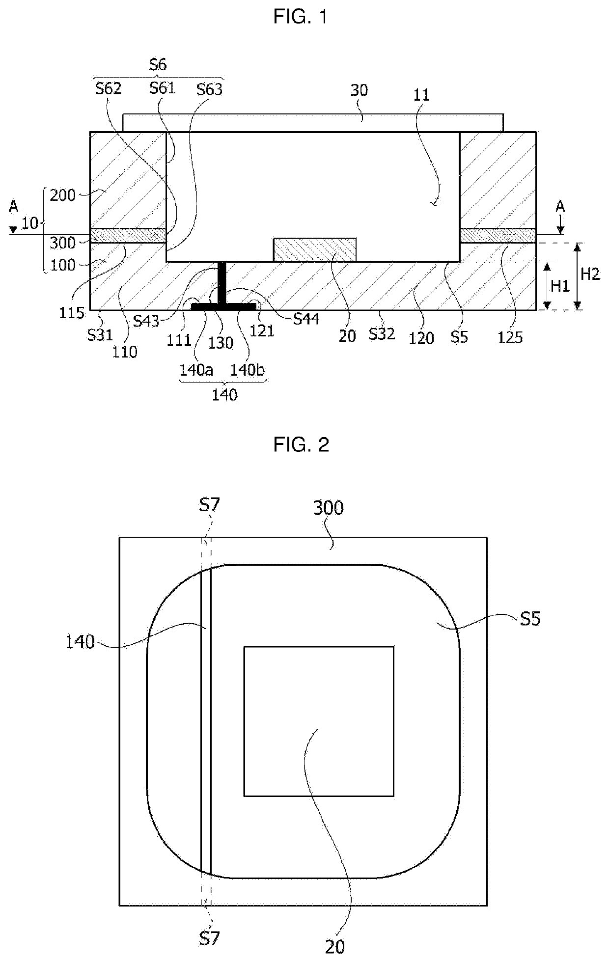
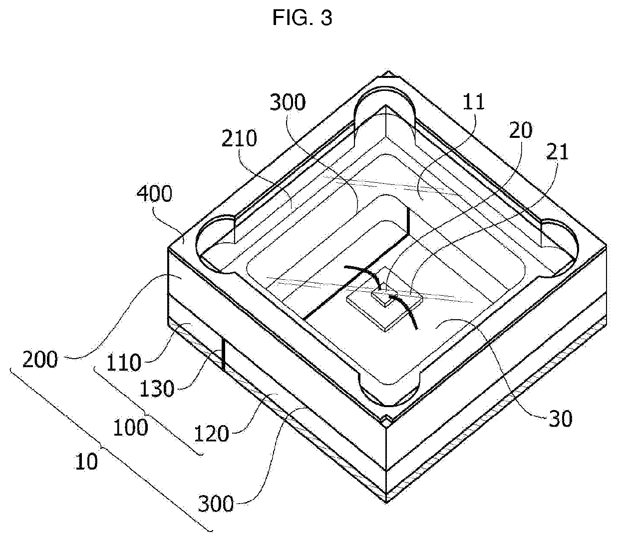
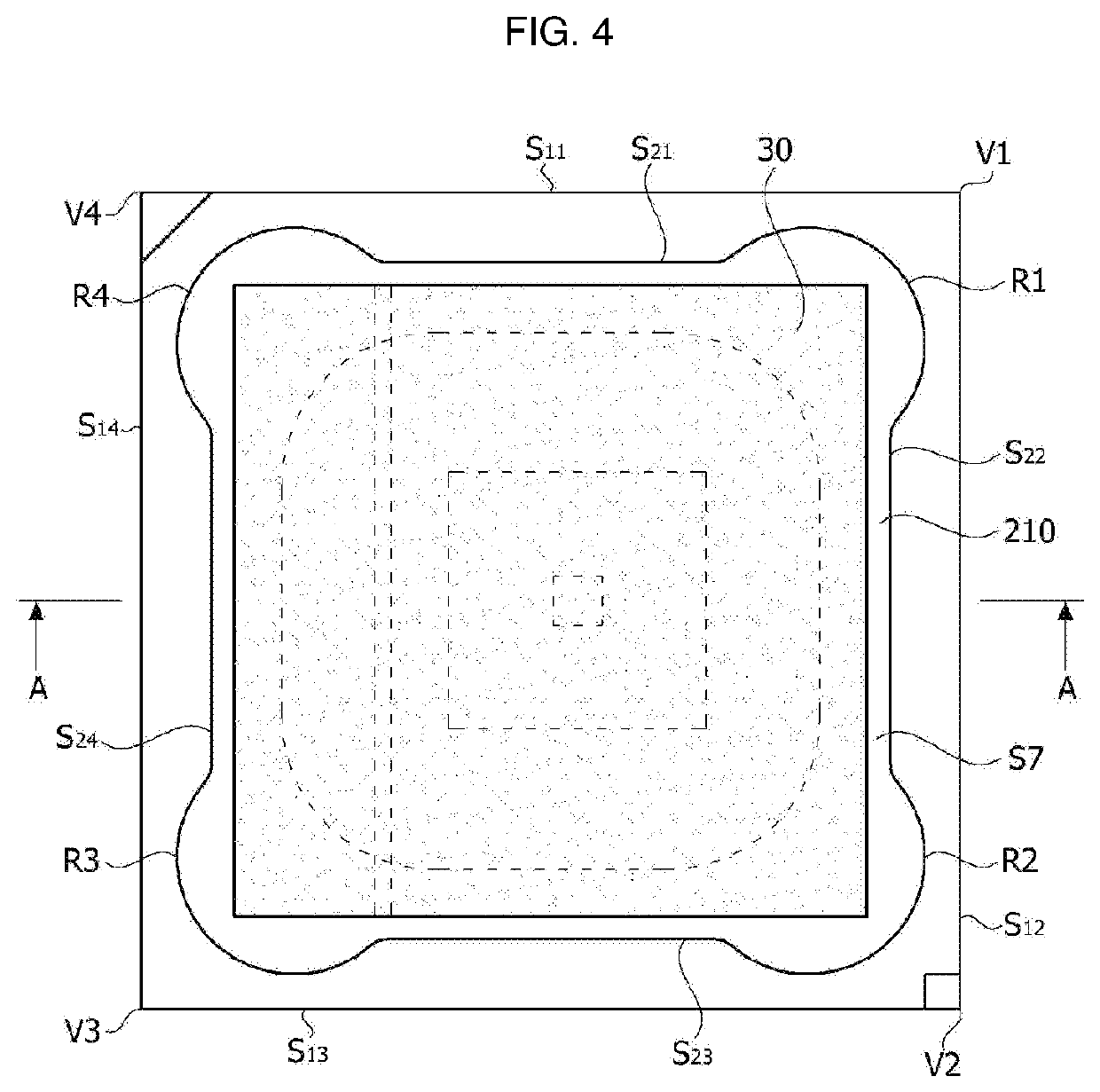
Disclosed in an embodiment is a light-emitting element package comprising: a body including a cavity; a light-emitting element arranged on the bottom surface of the cavity and including a first conductive type semiconductor layer, a second conductive type semiconductor layer and an active layer, which is arranged between the first conductive type semiconductor layer and the second conductive type semiconductor layer; and a light-transmitting member arranged on the upper part of the cavity, wherein the body includes: a lower body including the bottom surface of the cavity; an upper body including the lateral surface of the cavity; and a first insulating layer arranged between the lower body and the upper body, the lower body includes a first conductive body and a second conductive body insulated and arranged together with the first conductive body, the first conductive type semiconductor layer is electrically connected with the first conductive body, the second conductive type semiconductor layer is electrically connected with the second conductive body, and the height from the lower surface of the lower body to the bottom surface of the cavity is less than the height from the lower surface of the lower body to the lower surface of the first insulating layer.

Description

CROSS-REFERENCE TO RELATED PATENT APPLICATIONS[0001]This application is a U.S. National Stage Application under 35 U.S.C. § 371 of PCT Application No. PCT / KR2019 / 002474, filed Mar. 4, 2019, which claims priority to Korean Patent Application No. 10-2018-0051257, filed May 3, 2018, whose entire disclosures are hereby incorporated by reference.TECHNICAL FIELD[0002]Embodiments relate to a light-emitting element package and a light-emitting element module including the same.BACKGROUND ART[0003]Light-emitting elements containing compounds, such as GaN, AlGaN, and the like, have many advantages such as wide and easily adjustable bandgap energy and the like and can be variously used as light-emitting devices, light-receiving devices, various diodes, and the like.[0004]In particular, a light-emitting element such as a light-emitting diode or a laser diode using a Group III-V or II-VI compound semiconductor material may realize various colors, such as red light, green light, and a blue light,...

Claims


Application Information

Patent Timeline
IPC IPC(8): H01L33/48H01L33/62H01L33/64A61L2/26A61L2/10A61L9/20
CPCH01L33/486H01L33/62H01L33/644A61L2/26A61L2209/12A61L9/20A61L2202/11A61L2202/24A61L2/10H01L33/58H01L33/20H01L33/483H01L33/64H01L33/36
Inventor LEE, KOH EUN
Owner SUZHOU LEKIN SEMICON CO LTD
Learn More