
Acoustic filter for a coaxial electro-acoustic transducer

a coaxial electro-acoustic transducer and filter technology, applied in the field of loudspeakers, can solve the problems of prone to mismatch in coaxial alignment dip in frequency response, etc., and achieve the effect of restoring the response perceived by the listener, reducing cross-talk, and reducing the cost of operation

Pending Publication Date: 2021-09-23
BLUEPRINT ACOUSTICS
View PDF0 Cites 0 Cited by
  • Summary
  • Abstract
  • Description
  • Claims
  • Application Information

AI Technical Summary

Benefits of technology

The patent describes a new design for a loudspeaker that can boost the output of low-frequency drivers and also contribute to tuning the resonating system to a specific frequency. By using a Helmholtz resonator, the loudspeaker can create a seamless connection between high- and low-frequency drivers while also minimizing cross-talk between them. The design also includes a baffle body that converts low-frequency response to half-space radiation, providing another 6 dB of output capability. Overall, this new design improves the sound quality and clarity of the loudspeaker.

Problems solved by technology

However such coaxial alignment may be prone to mismatch especially when a large diameter driver having relatively low frequency response (low frequency driver) is aligned with a small diameter driver having relatively high frequency response (high frequency driver).
A problem may arise because the high frequency driver typically needs to have a small diameter in order to remain omni-directional to a desired high frequency, while the low frequency driver typically needs to have a large diameter to reach down to a desired low frequency.
As a result useful frequency range of the high frequency driver may not reach down to the piston range of the low frequency driver.
Stretching the response of the low frequency driver up in frequency beyond its piston range may cause an inconsistent polar pattern and / or a polar pattern mismatch between drivers and potentially a dip in the frequency response.
Stretching the response of the high frequency driver down in frequency beyond its effective output capability may cause a dip in the frequency response.
Interaction between the drivers may also cause a loss of output at certain frequencies including potentially a relatively sharp dip in frequency response.
If the low frequency driver is not acoustically rolled off it may mix highly directional acoustic radiation in the band of the high frequency driver which is audible at relatively low levels and may further contribute to an audible mismatch between drivers

Method used


Image

  • Acoustic filter for a coaxial electro-acoustic transducer
  • Acoustic filter for a coaxial electro-acoustic transducer
  • Acoustic filter for a coaxial electro-acoustic transducer

Examples


Embodiment Construction

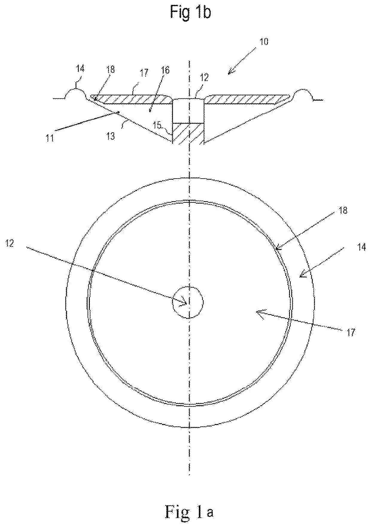
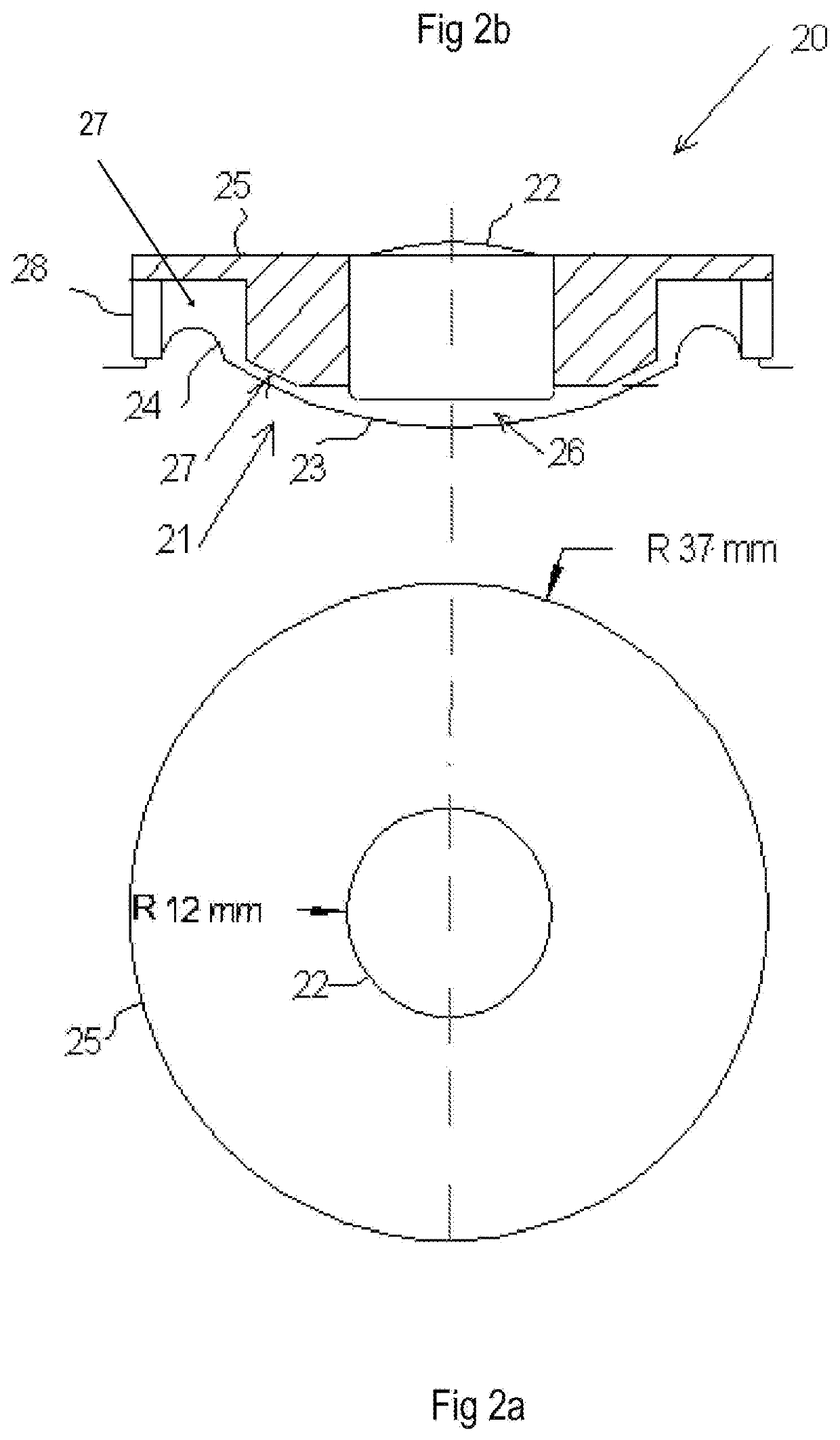
[0032]Preferred embodiments of the present invention will now be described in conjunction with the accompanying drawings. The attached drawings are intended to show the breadth of scope of the present invention. In particular FIGS. 1a and 1b show a pedestal mounted tweeter as is common in the art and FIGS. 2a and 2b show an independently mounted tweeter.

[0033]FIGS. 1a and 1b show coaxial transducer 10 comprising a relatively low frequency driver such as a mid-range driver 11 and a relatively high frequency driver such as a tweeter 12. The cone 13 of mid-range driver 11 is shown together with its surround 14. The remaining parts of mid-range driver 11 are not shown as they do not form part of the acoustic crossover filter. A person skilled in the art may readily identify mid-range driver 11 from the parts shown in FIGS. 1a and 1b.

[0034]Tweeter 12 is shown mounted on pedestal 15 which passes through cone 13 of mid-range driver 11. Helmholtz resonator chamber 16 is formed between baff...


PUM


Abstract

An acoustic filter suitable for an electro-acoustic transducer is provided. The acoustic filter has a relatively high frequency driver and a relatively low frequency driver situated on a common axis. The acoustic filter includes a baffle body having an outer side and an inner side, such that said outer side serves as a baffle for said high frequency driver and said inner side forms a first wall of at least one Helmholtz resonator including a chamber and a vent duct communicating with said chamber.

Description

TECHNICAL FIELD[0001]The present invention relates to loudspeakers and in particular to an acoustic filter for a coaxial electro-acoustic transducer.DEFINITIONS[0002]Throughout this specification “electro-acoustic driver” or “driver” includes a loudspeaker transducer. “Coaxial driver” includes two or more drivers in a composite or substantially coaxial alignment or structure. “Loudspeaker” includes one or more drivers mounted in an enclosure or baffle. “Piston range” includes a range of frequencies wherein the corresponding wavelength is greater than the circumference of a driver. The upper limit of piston range is sometimes defined as the frequency at which ka=1 wherein k=wave number (2 pi / wavelength) and a=piston radius. Circumference of a driver includes its effective diameter as understood in the art multiplied by pi.[0003]A crossover defines the point or region in which one frequency band interfaces with another. Accordingly, the adjoining frequency bands may be referred to as ...

Claims


Application Information

Patent Timeline
IPC IPC(8): H04R1/28H04R1/24H04R3/14
CPCH04R1/2869H04R3/14H04R1/2849H04R1/24H04R1/2819
Inventor VELICAN, ZELJKO
Owner BLUEPRINT ACOUSTICS
Learn More