
Refrigeration apparatus

Pending Publication Date: 2021-09-16
TRANE INT INC
View PDF8 Cites 0 Cited by
  • Summary
  • Abstract
  • Description
  • Claims
  • Application Information

AI Technical Summary

Benefits of technology

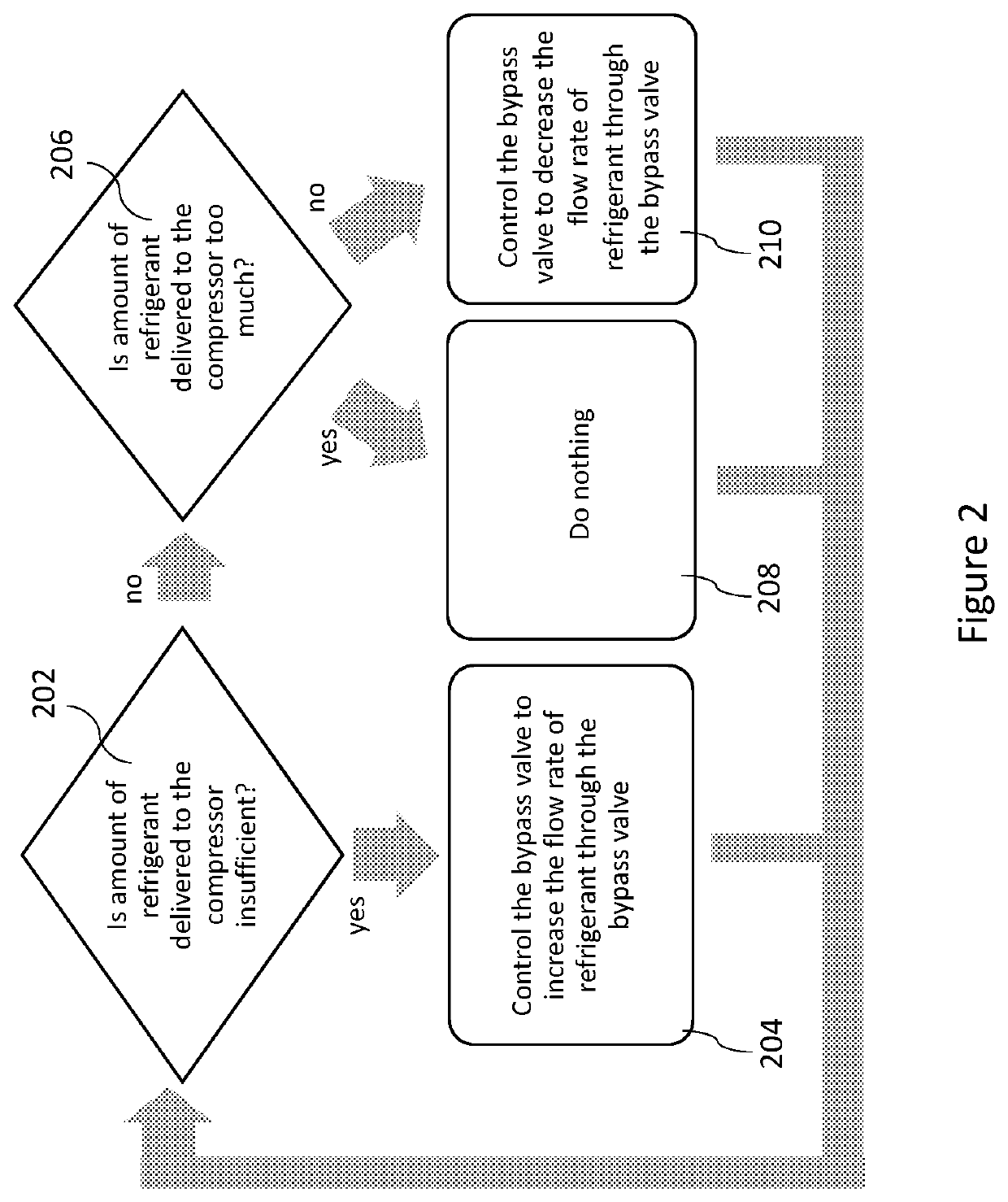
The patent is about a method for controlling the flow of refrigerant in a refrigeration system. The technical effect of the patent is to provide a way to prevent excessive refrigerant from being delivered to the compressor, which could cause damage or performance issues. This is achieved by adjusting the flow of refrigerant through a bypass valve that controls the path of the refrigerant in the system.

Problems solved by technology

Components of the compressor get hot during use, and requiring cooling.
However, it is possible under certain conditions for the amount of refrigerant directed to the compressor to be insufficient to cool the components of the compressor.

Method used


Image

  • Refrigeration apparatus
  • Refrigeration apparatus
  • Refrigeration apparatus

Examples


Embodiment Construction

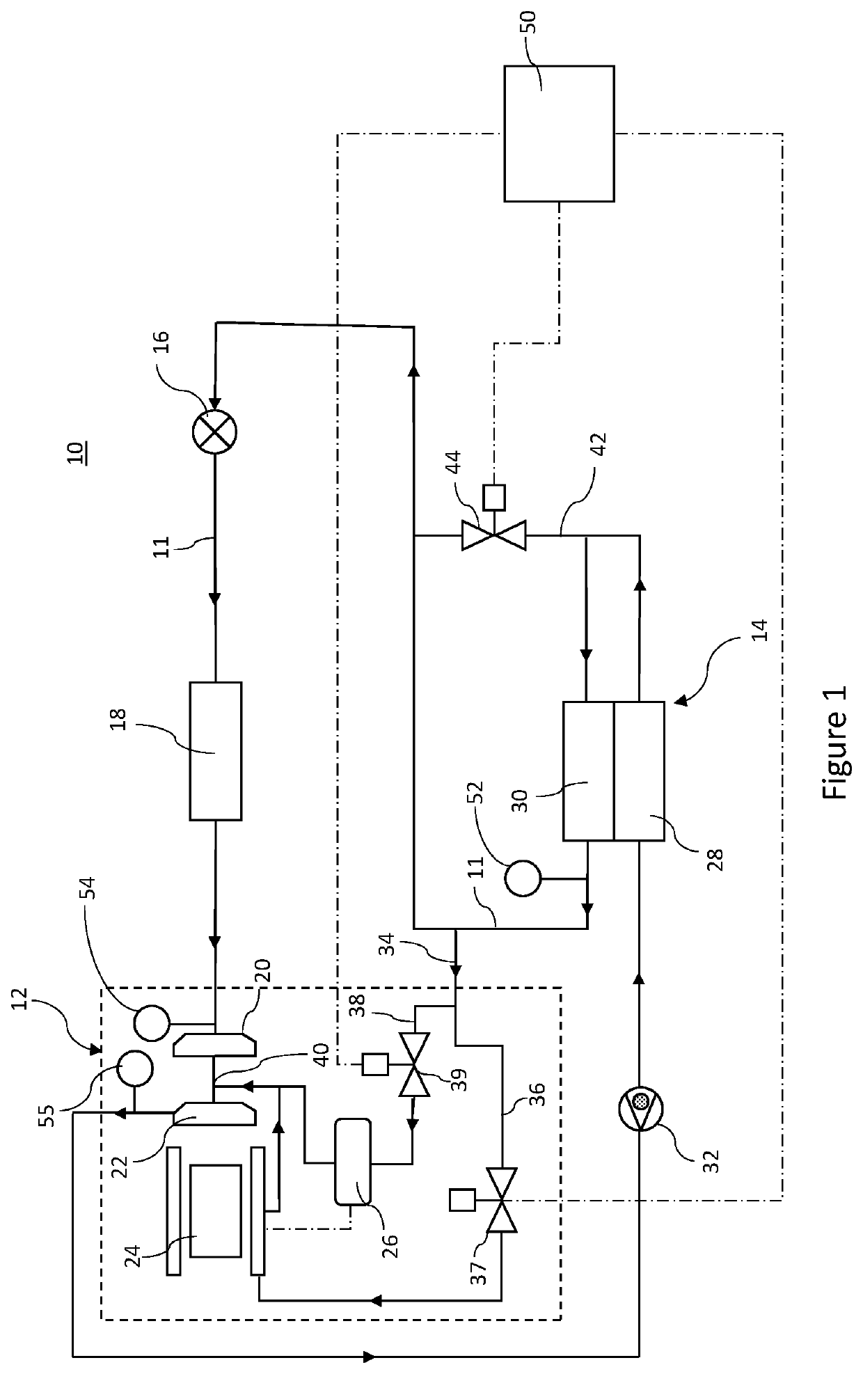
[0025]FIG. 1 shows an example refrigeration apparatus 10 comprising a refrigerant circuit. The refrigeration circuit comprises a compressor 12, a condensing device 14, an expansion valve 16 and an evaporator 18, which are fluidically connected to one another in series and in that order by a main refrigerant line 11, where the evaporator is connected to the compressor 12 to form a circuit.

[0026]The compressor 12 in this example is a two-stage compressor comprising a first stage compressor fan 20 and a second stage compressor fan 22. In other examples, the compressor may have only one stage or the compressor may have more than two stages.

[0027]The compressor 12 comprises a motor 24 which is configured to drive the first stage compressor fan 20 and the second stage compressor fan 22. The motor 24 is connected to an inverter 26 which is configured to control the speed of the motor 24.

[0028]The condensing device 14 is disposed downstream of the compressor 12, and comprises two stages of ...


PUM


Abstract

There is disclosed a refrigeration apparatus comprising a refrigerant circuit, the refrigerant circuit comprising a compressor comprising a compressor fan and a motor to drive the compressor fan; a condensing device disposed downstream of the compressor, the condensing device comprising a condenser and a sub-cooler; an expansion valve disposed downstream of the condensing device; an evaporator disposed between the expansion valve and the compressor; and a main refrigerant line fluidically connecting, in a loop in series: the compressor, condensing device, expansion valve and evaporator. A motor cooling line comprising a motor cooling valve fluidically connects the sub-cooler to the motor to tap refrigerant from the main refrigerant line to cool the motor and is further connected to the main refrigerant line at a return point which is upstream of the compressor fan to return refrigerant to the main refrigerant line at the compressor fan. A bypass line fluidically connects an outlet of the condenser to the expansion valve to bypass the sub-cooler, wherein the bypass line comprises a bypass valve to selectively permit refrigerant in the main refrigerant line to bypass the sub-cooler.

Description

FIELD OF INVENTION[0001]The present invention relates to a refrigerant apparatus and a method of operating a refrigeration apparatus.BACKGROUND[0002]Refrigeration units typically comprise a compressor, a condenser, an expansion valve and an evaporator connected in series through which refrigerant flows. Ambient air flows over the condenser to cool pressurised refrigerant in the condenser, and air or water to be cooled flows over the evaporator to transfer heat to the refrigerant in the evaporator, to thereby cool the air.[0003]Components of the compressor get hot during use, and requiring cooling. Refrigerant from the condenser may be passively driven to the compressor and used to cool the components of the compressor. However, it is possible under certain conditions for the amount of refrigerant directed to the compressor to be insufficient to cool the components of the compressor. Previously considered methods of operating a refrigeration unit have relied on moving away from the m...

Claims


Application Information

Patent Timeline
IPC IPC(8): F25B41/20F25B13/00
CPCF25B41/20F25B13/00F25B1/005F25B49/02F25B2600/05F25B31/026F25B40/02F25B2400/0417F25B2600/2501F25B2700/195F25B2700/197F25B2700/1931F25B2700/1933F25B2600/2519F25B31/006F25B41/40
Inventor RAIMBAULT, YVES JACQUESTISSERAND, PHILIPPE DEL MARCEL
Owner TRANE INT INC
Learn More