Heat exchanger and method of operating a heat exchanger

a heat exchanger and heat exchanger technology, applied in the field of heat exchangers, can solve the problems of comparatively low coolant temperature and comparatively inefficientness

Active Publication Date: 2021-09-09
HANON SYST
View PDF0 Cites 0 Cited by
  • Summary
  • Abstract
  • Description
  • Claims
  • Application Information

AI Technical Summary

Problems solved by technology

In this case, the coolant in the heat exchanger must absorb heat energy, which is possible comparatively inefficiently due to the associated high viscosity.
This may be advantageous

Method used


Image

  • Heat exchanger and method of operating a heat exchanger
  • Heat exchanger and method of operating a heat exchanger
  • Heat exchanger and method of operating a heat exchanger

Examples


Embodiment Construction

[0004]Against this background, the invention is based on the object of providing a heat exchanger that can be operated efficiently over a wide temperature range, as well as a method of operating the heat exchanger.

[0005]This object is solved firstly by the heat exchanger as disclosed herein.

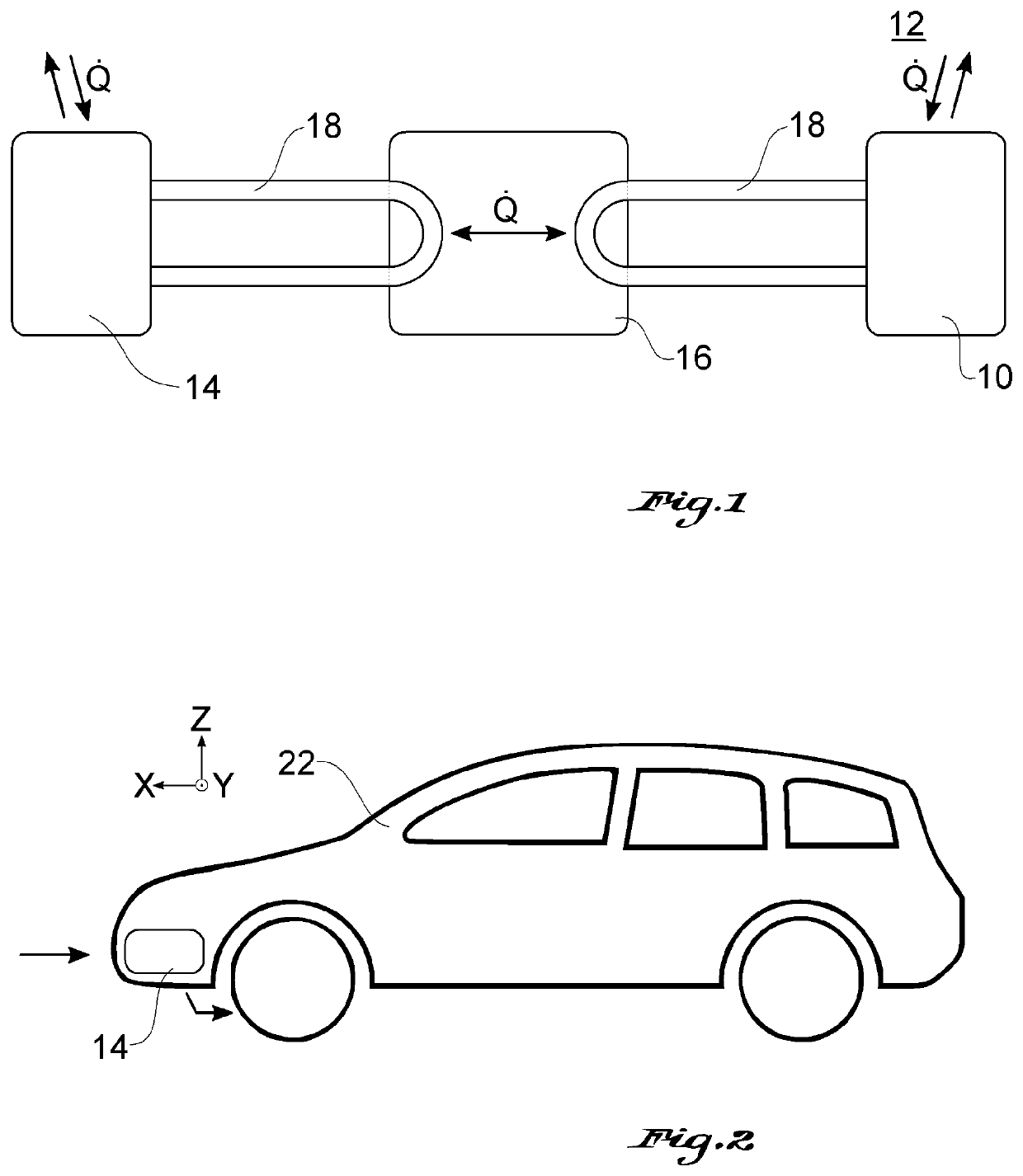
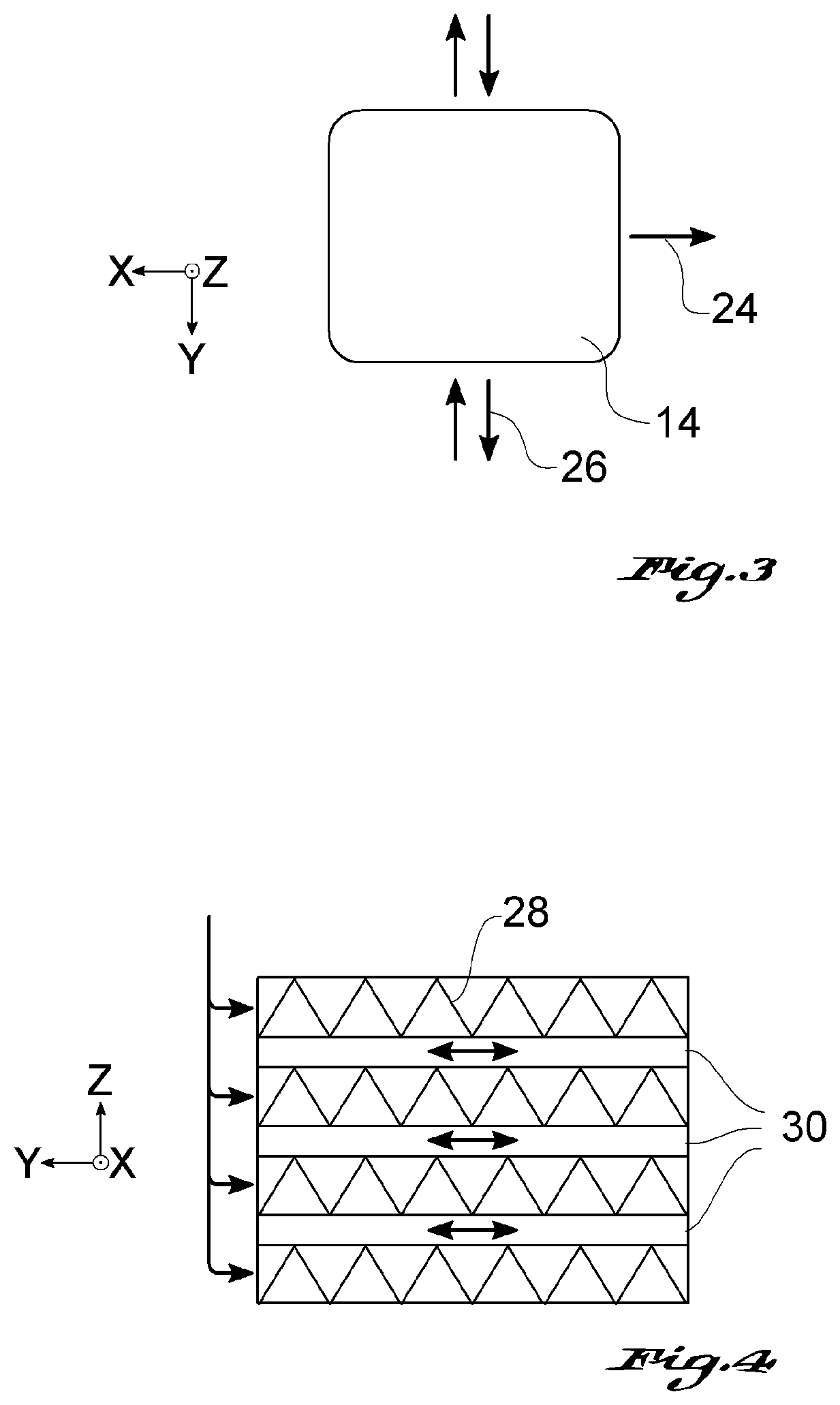
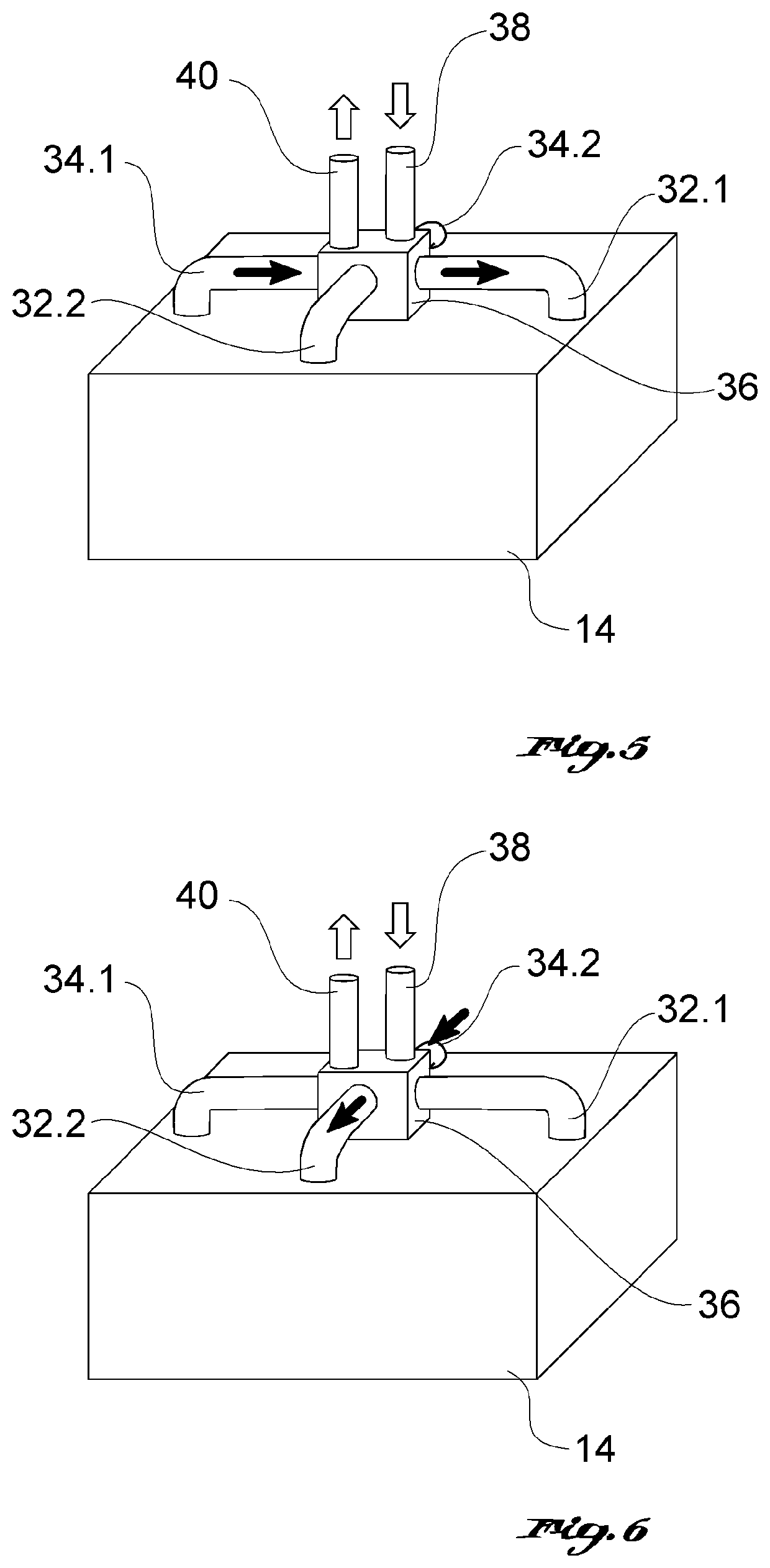
[0006]The heat exchanger accordingly has flow channels for coolants, which flow channels comprise turbulence elements having a different flow resistance depending on the direction of flow. According to the invention, the coolant flow can be passed through the heat exchanger in different directions. As a result of this, the generation of turbulence can be varied essentially by changing the direction of flow and, in particular, the viscosity of the coolant present at a given time can be adapted.

[0007]In other words, as described in more detail below, provisions are made to pass the coolant at a comparatively high viscosity through the flow channels of the heat exchanger such that there is a compara...


PUM


Abstract

A heat exchanger has flow channels for coolants, which flow channels include turbulence elements having a different flow resistance depending on a direction of a flow, wherein the flow can be passed through the heat exchanger in different directions. As part of a method of operating the heat exchanger, the heat exchanger is flowed through in different directions using a pump that can be operated in different directions.

Description

CROSS REFERENCE TO RELATED APPLICATIONS[0001]This patent application claims the benefit of German Patent Application No. DE 10 2020 202 835.4 filed on Mar. 5, 2020, the entire disclosure of which is hereby incorporated herein by reference.TECHNICAL FIELD[0002]The invention relates to a heat exchanger, in particular for use in an automobile for cooling a coolant, as well as to a method of operating a heat exchanger.PRIOR ART[0003]Heat exchangers are used in particular in automobiles in the front area of the vehicle to cool a coolant by means of the air flowing through. Cooling the interior of a vehicle can be ensured by means of an interconnected heat pump and a separate circuit. In electric or hybrid vehicles, cooling of the battery can additionally take place. Here, the case may arise that the battery has to be heated in certain operating conditions, and thus the coolant has to pass through the heat exchanger at extremely low temperatures due to the extraction of thermal energy in ...

Claims


Application Information

Patent Timeline
IPC IPC(8): F28F9/24F28F3/04F28F27/02F28F9/02
CPCF28F9/24F28F3/044F28F27/02F28F2250/102F28F2215/00F28F2250/08F28F9/0202F28D1/0213F28F13/12B60K11/04F28D9/005F28F3/027H01M2220/20H01M10/625Y02E60/10
Inventor MARTINI, JOERGPAULS, CHRISTOPH
Owner HANON SYST
Why Eureka
Try Eureka