
Systems and methods for light deactivation and removal of light deactivated adhesive drapes

Pending Publication Date: 2021-09-02
KCI LICENSING INC
View PDF0 Cites 0 Cited by
  • Summary
  • Abstract
  • Description
  • Claims
  • Application Information

AI Technical Summary

Benefits of technology

The patent describes a system for easily removing a light sensitive adhesive drape from a patient. The adhesive is deactivated when exposed to UV or visible light, and the drape can be removed without having to turn the patient over for a long time. The system can use a low power battery and has minimal leakage. The adhesive can be removed using a switchable adhesive that doesn't require any additional steps for the patient and results in a comfortable and safe removal of the drape.

Problems solved by technology

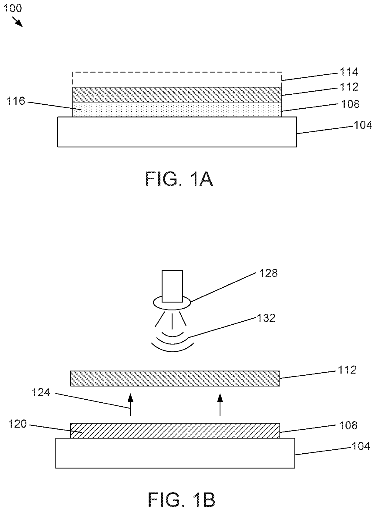
However in certain larger embodiments, such as a back or sacral dressing, or in patients with larger dressing areas, it may be quite inconvenient or time-consuming to remove the dressing without turning the patient over for a certain length of time (e.g., about 5 minutes) for the light sensitive skin adhesive to deactivate.
This task may be strenuous for both the caregiver and the patient, especially for patients who are elderly, weak, or have traumatic wounds.
Any leak which results in a pressure drop of more than 1 cc / min may result in a leak alarm and the suspension of therapy.
However, while this combination may excel at reducing or eliminating leakage, it may result in a dressing that can be very painful for dressing removal and may result in damage to delicate or damaged skin.
A switchable adhesive where the user is required to use a separate tool to trigger the release of the dressing can address many of these issues but these systems may be expensive and may also require the patient / user to have to remember another process step when they wish to remove the dressing prior to dressing change.

Method used


Image

  • Systems and methods for light deactivation and removal of light deactivated adhesive drapes
  • Systems and methods for light deactivation and removal of light deactivated adhesive drapes
  • Systems and methods for light deactivation and removal of light deactivated adhesive drapes

Examples


Embodiment Construction

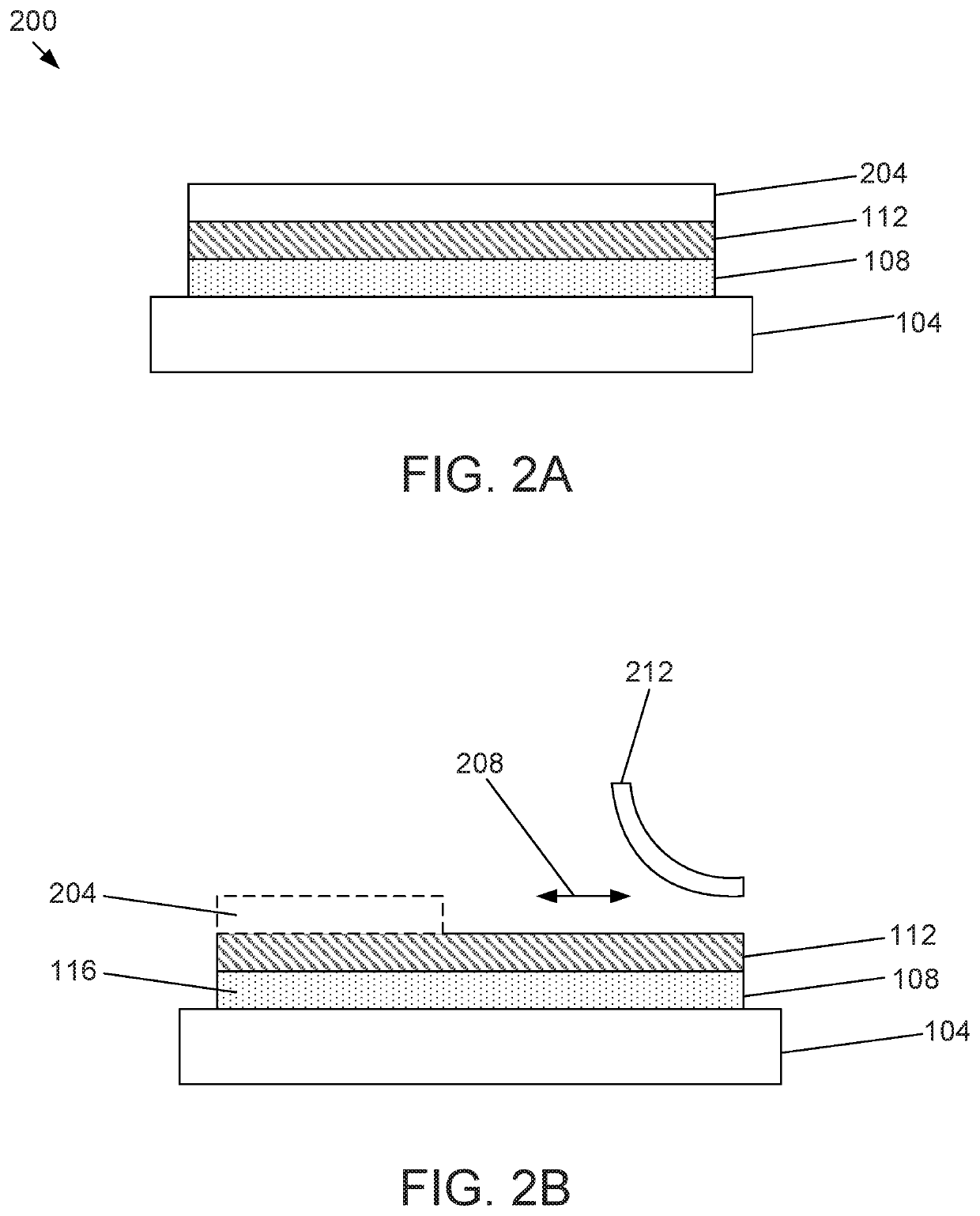
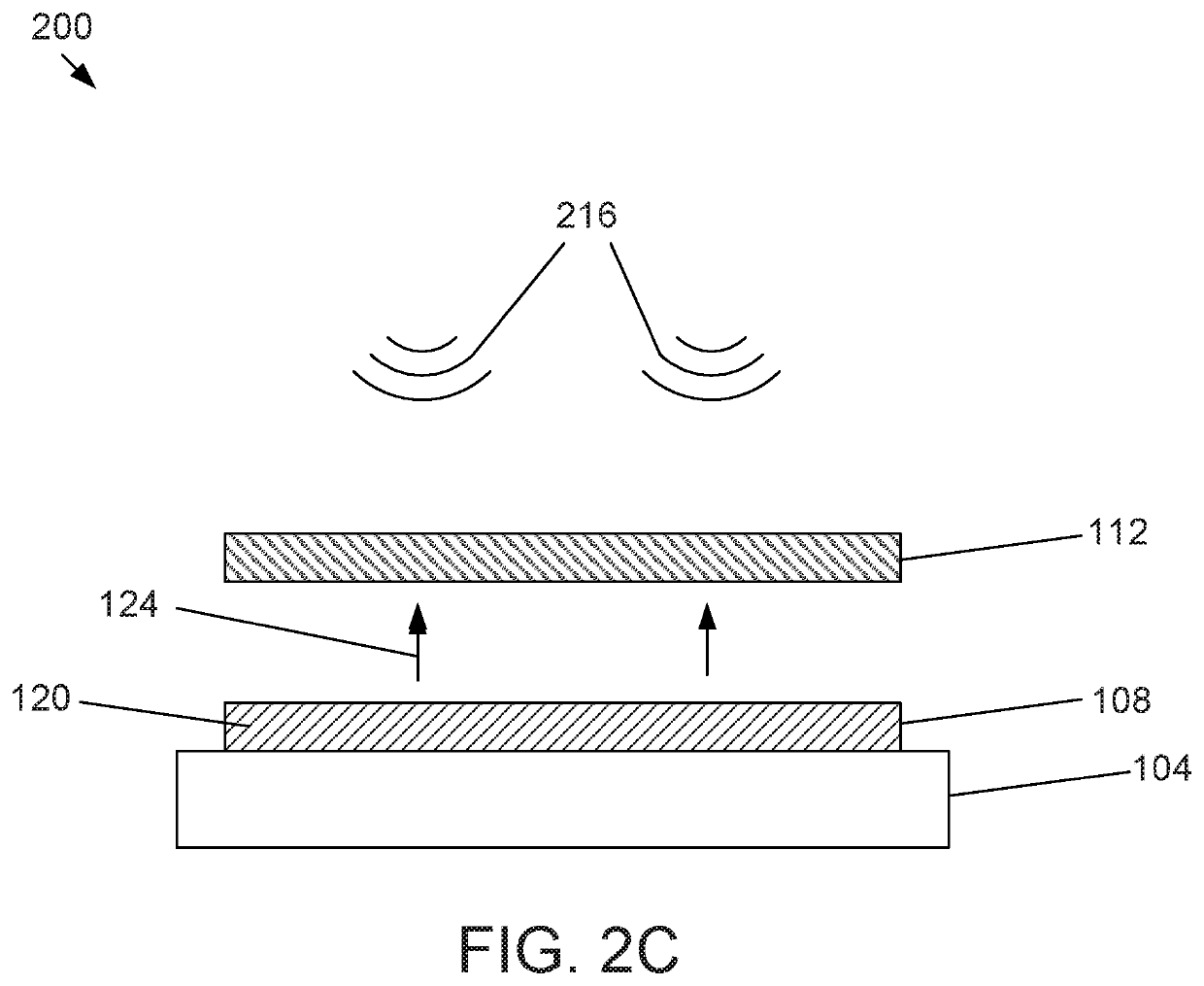
[0030]In the following detailed description of the preferred embodiments, reference is made to the accompanying drawings that form a part hereof, and in which is shown by way of illustration specific preferred embodiments in which the invention can be practiced. These embodiments are described in sufficient detail to enable those skilled in the art to practice the invention, and it is understood that other embodiments can be utilized and that logical structural, mechanical, electrical, and chemical changes can be made without departing from the spirit or scope of the invention. To avoid detail not necessary to enable those skilled in the art to practice the invention, the description can omit certain information known to those skilled in the art. It is understood that reference to a feature by numeric designation does not necessarily refer only to any particular embodiment depicted in a drawing. The following detailed description is, therefore, not to be taken in a limiting sense, a...


PUM


Abstract

Provided herein is a system and method for mitigating premature light deactivation of light deactivated adhesive drapes. One aspect provides a system comprising a drape, a photosensitive adhesive layer, a release agent, and an optical fiber mesh layer configured as a light pipe, where the system is adapted to be coupled to a tissue site and released therefrom upon or after exposure to an external stimulus such as certain wavelengths of light. Another aspect includes a pipe light pipe, as an alternative to the optical fiber mesh layer. The systems may have a removable blocking layer to prevent the photosensitive adhesive from being exposed to deactivation wavelengths prematurely. Another aspect provides a method for application and removal of a drape using the light pipe to transport or route light to the drape to deactivate the photosensitive adhesive layer and promote easy, clean, and less painful removal of the drape.

Description

CROSS-REFERENCE TO RELATED APPLICATIONS[0001]This application claims priority to and the benefit of U.S. Provisional Application No. 62 / 699,864, filed Jul. 18, 2018, the contents of which is incorporated into the present application by reference.BACKGROUND1. Field of Invention[0002]The present application relates generally to the field of tissue treatment, and more specifically to a system and method for facilitating the application and removal of a drape from a tissue site.2. Description of Related Art[0003]Systems and devices currently exist for the treatment of tissue, such as wound tissue and skin tissue. Some current tissue treatment systems require the use of an adhesive drape to secure all or a portion of the tissue treatment system to a tissue site. For example, an adhesive drape can be used to secure a gauze portion of a bandage to a wound site by adhering to the skin or other tissue surrounding the wound. Drapes intended for use with negative pressure wound therapy (NPWT) ...

Claims


Application Information

Patent Timeline
IPC IPC(8): A61B46/20A61B46/00C09J7/30C09J7/40
CPCA61B46/20A61B46/40C09J2301/502C09J7/403A61B2046/205C09J7/30A61F13/00051A61F2013/00187A61F13/0246
Inventor ROBINSON, TIMOTHY MARKLOCKE, CHRISTOPHER BRIANLONG, JUSTIN ALEXANDERPRICE, ASHWATHA
Owner KCI LICENSING INC
Learn More