
Hdr color processing for saturated colors

Active Publication Date: 2021-08-26
KONINKLJIJKE PHILIPS NV
View PDF13 Cites 0 Cited by
  • Summary
  • Abstract
  • Description
  • Claims
  • Application Information

AI Technical Summary

Benefits of technology

The patent describes new techniques to improve images that have been downmapped for lower peak brightness. These techniques allow for better quality in the image without causing problems in other situations. The techniques involve calculating certain values called G_PQ, which can be used to adjust the image's brightness. These values are based on the video content creator's luma mappings, which are used to compress the image. These techniques help to make the image look better, without causing other problems that may occur when adjusting the brightness.

Problems solved by technology

High dynamic range video handling (coding, display adaptation and the like) is a quite recent technical field, which still comes with several unsettled questions and problems.
There have been a number of movies which have been created and communicated, and also a few early-days broadcasts, and though in general the result is great, there are also still possibilities to further improve on certain aspect, ergo, the technology is not in a phase of being largely settled currently.
Indeed, the problem with image processing is that there is always an almost infinite variability of the content (the input video may be a dark Hollywood movie of a burglary happening at nighttime, or a youtube movie where one follows the brightly colored computer graphics of somebody playing an on-line game, etc.
(then the functions will have a somewhat different shape, but that display adaptation detail is also not useful to understand the present application's new technical principles, and can be found in said ETSI standard).
However, if one starts to do a (needed) more advanced decoding for the present HDR era videos, some inconvenient problems may occur.
This gives rise to several issues.
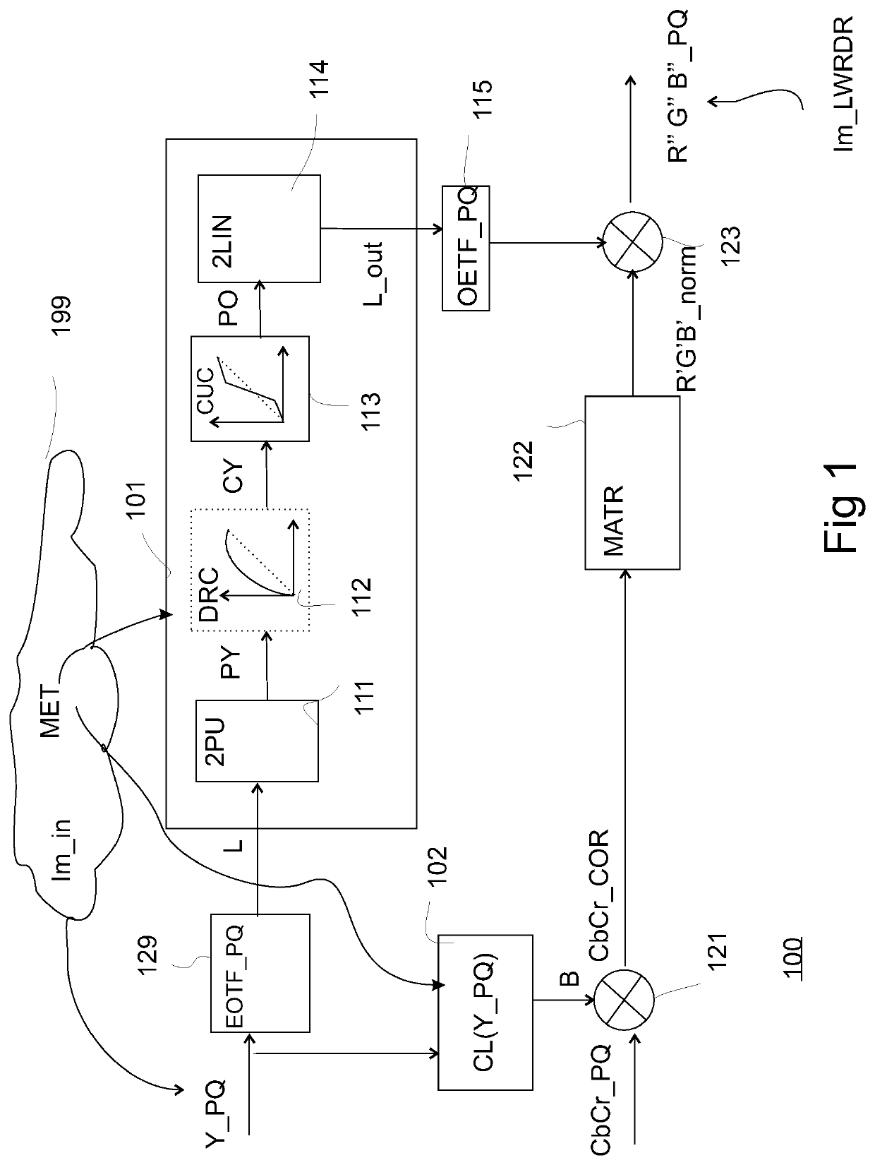
Firstly we don't know exactly which luminance we have from only looking at the luma value Y, i.e. by applying the EOTF to Y, and this might already give problems in frameworks which do not handle the 3D colorimetry in a natural 3D manner, but for pragmatic reasons in a 1D+2D manner, like the decoder of FIG. 1.
Indeed, in theory one can do everything correctly if one brings in the corrective dependency of the particular values for the pixel of Cb and Cr, but that may not be possible in some predesigned color processing topologies.
Nevertheless, this is normally not a (real) problem, which pragmatically looking at technology is not seen of sufficient error magnitude to be a reasonable concern, as was tested over the past years with many different kinds of image content.
I.e., especially changes in output color, and in particular luminance, along the object due to this total processing can be seen as problematic.
As will be shown below this can lead to processing errors in our SLHDR decoding approach, which will need to be counter-corrected, and specifically counter-corrected as taught and claimed.
One might theoretically consider to just build a better, different 3D-based decoding system, which might readily solve the issues, but in actual technically limited already deployed video ecosystem (with separate luminance processing and chromatic processing) this is not as easily done in practice.
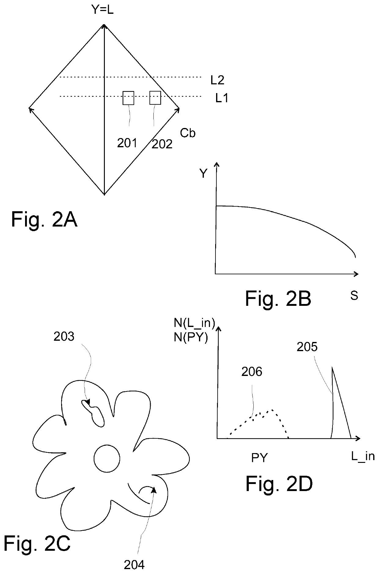
E.g., a video content creator may wish to make the colors of the secondary image determinable from the primary master HDR image excessively deep for some dark pixels, which may affect the quality of inverse luma mapping for decoding.

Method used


Image

  • Hdr color processing for saturated colors
  • Hdr color processing for saturated colors
  • Hdr color processing for saturated colors

Examples


Embodiment Construction

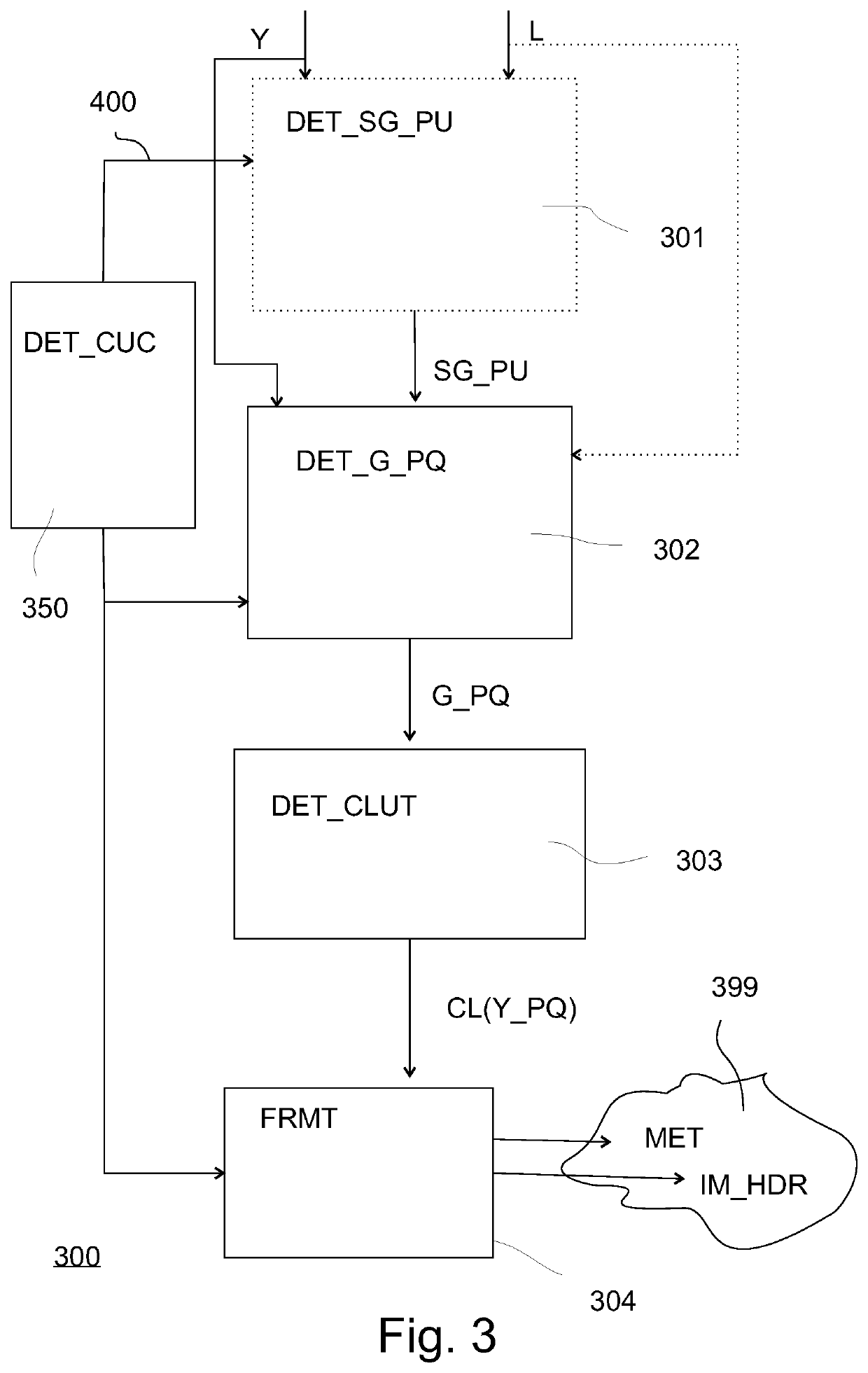
[0100]FIG. 3 elucidates how the modified encoder, compliant with our SLHDR HDR video encoding approach, works. At the encoding side one has, as input, the original master HDR image (e.g. a 5000 nit PB_C image as graded by a human color grader so that all objects in the various video images like e.g. bright explosions and dark shadowy areas in caves look optimal) available, so one has both the pixel luminances (L) and the corresponding lumas (Y) available. There is a luma mapping function determination circuit 350 comprised (or connected), which can determine the optimal e.g. S-shaped luma mapping curve as shown in and discussed with FIG. 4 (i.e. of circuit 113 in FIG. 1). Note that whereas we elucidate the principles with this S-shaped mapping function, the processing is generic whatever the function (it may even work on situations where it doesn't improve, but also not deteriorate). We needn't elaborate on the many ways in which this can be done by various embodiments developed by ...


PUM


Abstract

To mitigate some problems of the pixel color mapping being used in HDR video decoding of the type of SLHDR, a high dynamic range video encoding circuit (300) is taught, configured to encode a high dynamic range image (IM_HDR) of a first maximum pixel luminance (PB_C1), together with a second image (Im_LWRDR) of lower dynamic range and corresponding lower second maximum pixel luminance (PB_C2), the second image being functionally encoded as a luma mapping function (400) for decoders to apply to pixel lumas (Y_PQ) of the high dynamic range image to obtain corresponding pixel lumas (PO) of the second image,the encoder comprising a data formatter (304) configured to output to a video communication medium (399) the high dynamic range image and metadata (MET) encoding the luma mapping function (400),the functional encoding of the second image being based also on a color lookup table (CL(Y_PQ)) which encodes a multiplier constant (B) for all possible values of the pixel lumas of the high dynamic range image, and the formatter being configured to output this color lookup table in the metadata, characterized in that the high dynamic range video encoding circuit comprises: —a gain determination circuit (302) configured to determine a luma gain value (G_PQ) which quantifies a ratio of an output image luma for a luma position equal to a correct normalized luminance position divided by an output luma for the luma of the pixel of the high dynamic range image,wherein the high dynamic range video encoding circuit comprises a color lookup table determination circuit (303) configured to determine the color lookup table (CL(Y_PQ)) based on values of the luma gain value for various lumas of pixels present in the high dynamic range image.Similarly we teach how the same principles can be embodied in a SLHDR-type video decoder.

Description

FIELD OF THE INVENTION[0001]The invention relates to methods and apparatuses for doing dynamic range conversions involving changes of the luminance of pixels from an input image to the luminance of pixels of an output image, in particular when said images contain highly saturated pixel colors.BACKGROUND OF THE INVENTION[0002]High dynamic range video handling (coding, display adaptation and the like) is a quite recent technical field, which still comes with several unsettled questions and problems. Although HDR televisions are being sold for a few years now (typically with a maximum displayable luminance a.k.a. peak brightness of 1000 nit or Cd / m{circumflex over ( )}2 or less), the technology that comes before the pure displaying (content making, coding, color processing) still has a number of solutions to invent / improve and deploy. There have been a number of movies which have been created and communicated, and also a few early-days broadcasts, and though in general the result is gr...

Claims


Application Information

Patent Timeline
IPC IPC(8): H04N9/77H04N9/68H04N19/182H04N19/186H04N19/17H04N19/46
CPCH04N9/77H04N9/68H04N19/46H04N19/186H04N19/17H04N19/182H04N19/30H04N19/98
Inventor NIJLAND, RUTGER
Owner KONINKLJIJKE PHILIPS NV
Learn More