
Power Amplifier System and Transfer Learning-based Autotuning Optimization Method Thereof

a power amplifier and optimization method technology, applied in adaptive control, high-level techniques, instruments, etc., can solve the problems of complex compensation circuit parts, difficult optimization, and increase the power consumption of wireless transmitters, so as to facilitate the circuit tuning procedure and enhance performance.

Active Publication Date: 2021-08-19
MITSUBISHI ELECTRIC RES LAB INC
View PDF1 Cites 0 Cited by
  • Summary
  • Abstract
  • Description
  • Claims
  • Application Information

AI Technical Summary

Benefits of technology

The patent text describes a system and method for optimizing the performance of Digital Power Amplifiers (DPAs) used in mobile communication devices. The system includes a control circuit that receives input signals and transmits control signals to the DPA, based on an adaptive control algorithm that determines optimal parameters for controlling the DPA's operation. The control algorithm is trained using previous control parameters and performance data, and can adapt to changes in device parameters, phase delay, temperature, and input signals. The system can balance efficiency and gain or maximize efficiency under certain constraints, and can also optimize for Adjacent Channel Power Ratio (ACPR) to limit power emitted to adjacent channels. These technical effects improve the efficiency and performance of DPAs in a flexible and adaptive way, making them suitable for a wide range of mobile communication standards.

Problems solved by technology

The rapid growing of wireless communication data volume and rate significantly raise the power consumption in wireless transmitters, in which the power amplifier (PA) is the key component for energy consumption.
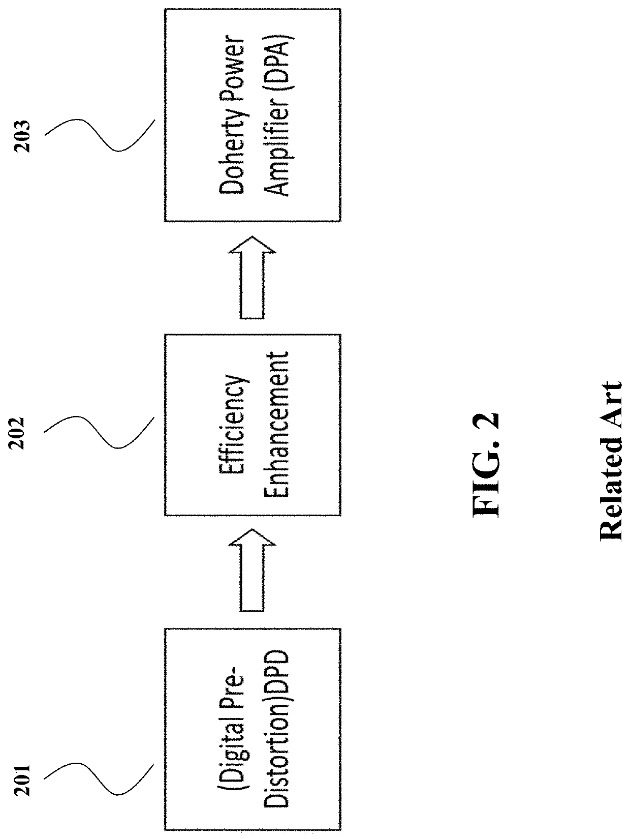
Although the DPA shows numerous advantages for efficiency enhancement, traditional analog DPA still suffers from imperfection which results in a degraded performance in terms of energy efficiency and operational bandwidth.
The compensation circuit part is also complicated and challenging to optimize, making DPA design cumbersome.
These are very limitations from pure analog based design.

Method used


Image

  • Power Amplifier System and Transfer Learning-based Autotuning Optimization Method Thereof
  • Power Amplifier System and Transfer Learning-based Autotuning Optimization Method Thereof
  • Power Amplifier System and Transfer Learning-based Autotuning Optimization Method Thereof

Examples


Embodiment Construction

[0029]Various embodiments of the present invention are described hereafter with reference to the figures. It would be noted that the figures are not drawn to scale elements of similar structures or functions are represented by like reference numerals throughout the figures. It should be also noted that the figures are only intended to facilitate the description of specific embodiments of the invention. They are not intended as an exhaustive description of the invention or as a limitation on the scope of the invention. In addition, an aspect described in conjunction with a particular embodiment of the invention is not necessarily limited to that embodiment and can be practiced in any other embodiments of the invention.

[0030]FIG. 1 is a block diagram of a digital power amplifier (DPA) module 100, according to some embodiments of the present invention. The DPA module 100 may be a digital power amplifier (DPA) module that is configured by multi-input power amplifiers 120 such as Doherty...


PUM


Abstract

A Digital Power-Amplifier (DPA) system includes a power amplifier (PA) circuit having control inputs and an output for generating output signals, and an adaptive control circuit that comprises an input interface, an output interface, a memory storing an adaptive control algorithm and a processor performing instructions based on the adaptive control algorithm in connection with the memory, wherein the input interface receives input-state signals and output signals of the DPA circuit, wherein the adaptive control algorithm determines, in response to the input-state signals and the output signals, control parameters of control signals transmitted to the control inputs from the output interface for controlling operations of the DPA circuit.

Description

FIELD OF THE INVENTION[0001]The present invention is related to a power amplifier system, and more particularly to a digital Doherty power amplifier system and a transfer learning-based autotuning optimization method of a power amplifier system for enhancing performance of radio frequency power amplifier.BACKGROUND OF THE INVENTION[0002]The rapid growing of wireless communication data volume and rate significantly raise the power consumption in wireless transmitters, in which the power amplifier (PA) is the key component for energy consumption. Several advanced techniques including Envelope Tracking (ET), Doherty Power Amplifier (DPA), Envelop Elimination and Restoration (EER) have been proposed to improve the Power Added Efficiency (PAE) of PA. Among these techniques, DPA is very promising thanks to its simple structure enabling high average efficiency, which is on the basis of active load modulation.[0003]Although the DPA shows numerous advantages for efficiency enhancement, tradi...

Claims


Application Information

Patent Timeline
Patent Type & Authority Applications(United States)
IPC IPC(8): H03F1/02H03F3/21G05B13/02
CPCH03F1/0288H03F2200/451G05B13/0265H03F3/21H03F1/0272H03F3/195H03F3/245Y02D30/70
Inventor MA, RUIBENOSMAN, MOUHACINEJEONG, SOYEON
Owner MITSUBISHI ELECTRIC RES LAB INC
Learn More