Continuously variable transmission for vehicle

Pending Publication Date: 2021-08-19
JATCO LTD +1
View PDF0 Cites 0 Cited by
  • Summary
  • Abstract
  • Description
  • Claims
  • Application Information

AI Technical Summary

Benefits of technology

The patent text describes a device that reduces the speed difference between two pulleys, which allows for a higher gear ratio in a vehicle transmission. This prevents the primary pulpy from rotating too quickly, which could cause damage. The technical effect of this device is improved control and efficiency of the vehicle's transmission.

Problems solved by technology

Moreover, in the towed state, the hydraulic pressure is not supplied to both of the pulley pressure receiving chamber of the primary pulley side, and the pulley pressure receiving chamber of the secondary pulley side.

Method used


Image

  • Continuously variable transmission for vehicle
  • Continuously variable transmission for vehicle
  • Continuously variable transmission for vehicle

Examples


Embodiment Construction

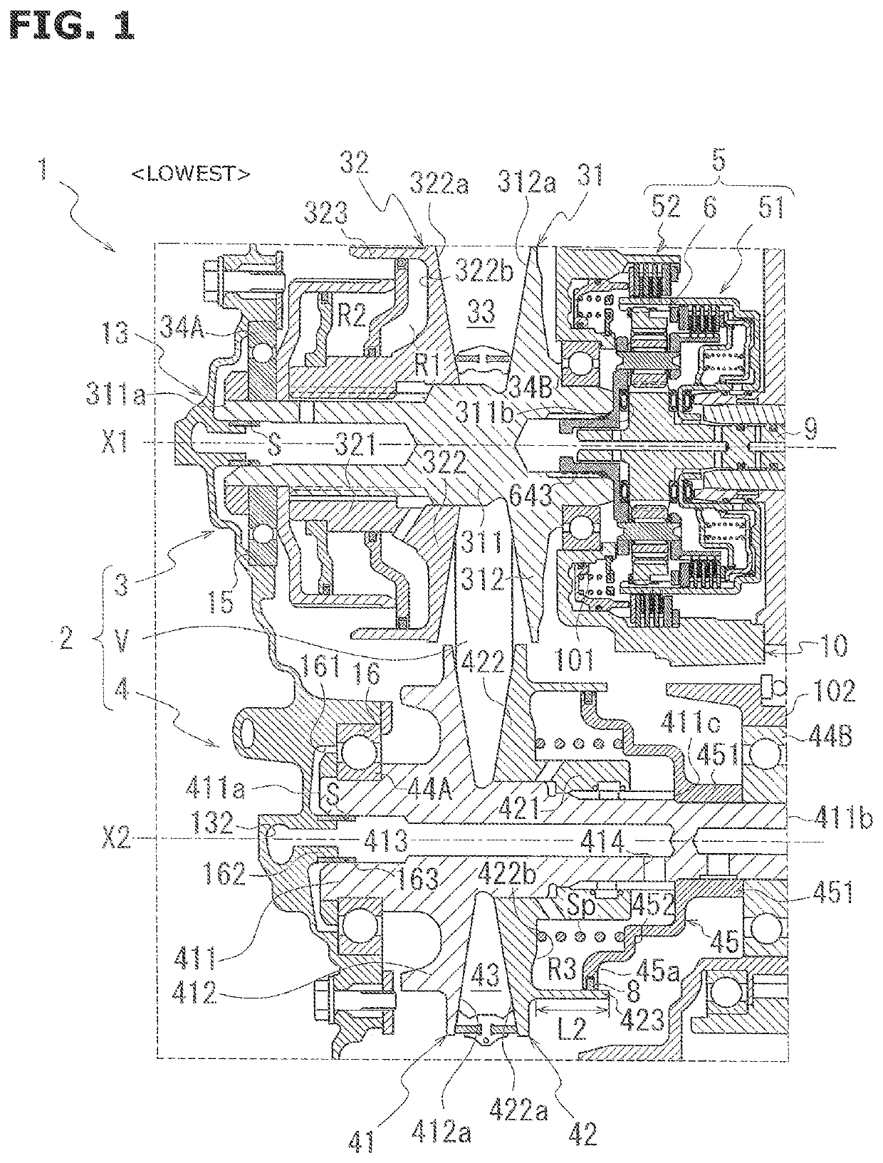
[0026]Hereinafter, a belt type continuously variable transmission 1 for a vehicle according to an embodiment of the present invention is explained.

[0027]FIG. 1 is a view for explaining a main part of the continuously variable transmission 1.

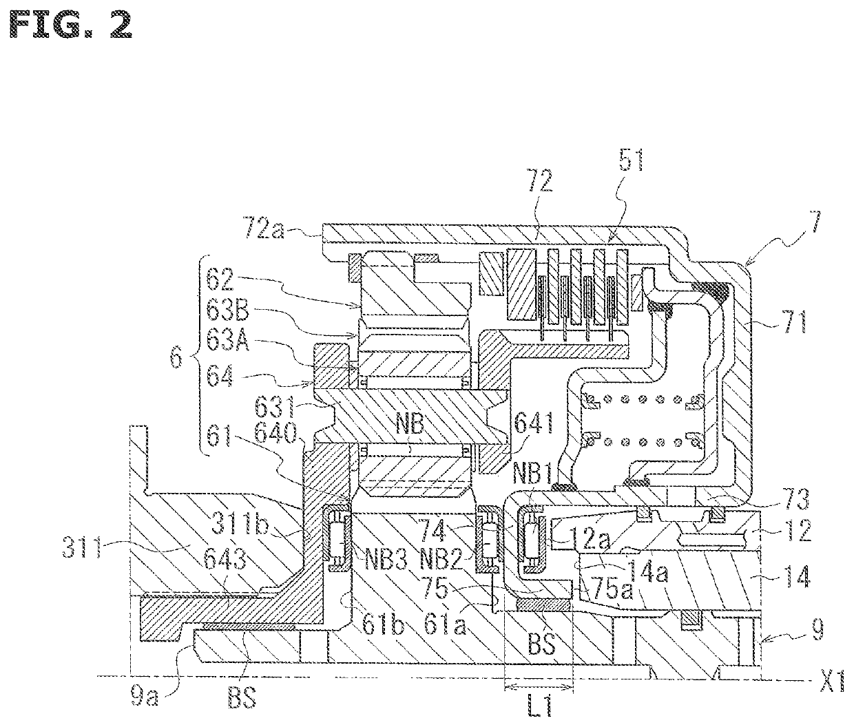
[0028]FIG. 2 is a view for explaining a main configuration around a planetary gear set 6 of a forward and backward switching mechanism 5.

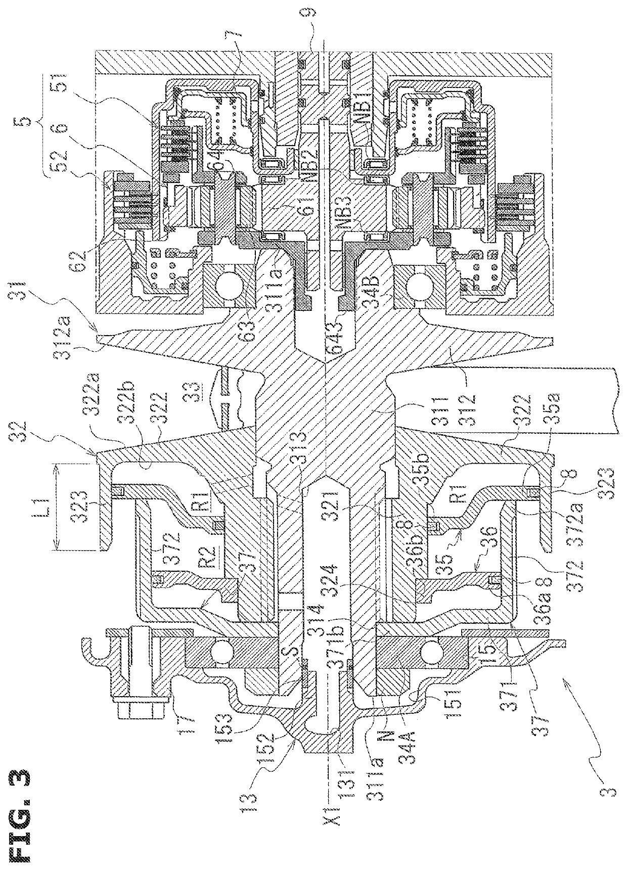
[0029]FIG. 3 is a view for explaining a portion around a primary pulley 3 and the forward and backward switching mechanism 4 of the continuously variable transmission 1.

[0030]As shown in FIG. 1, in the belt type continuously variable transmission 1, a rotation drive force of an engine (not shown) which is a driving source is inputted through a torque converter (not shown) to the forward and backward switching mechanism 5.

[0031]The forward and backward switching mechanism 5 includes a planetary gear set 6; a forward clutch 51; and a backward brake 52.

[0032]In the planetary gear set 6 of the forward and backward s...


PUM


Abstract

A continuously variable transmission for a vehicle includes: a variator including; a primary pulley, a secondary pulley, and an endless annular member wound around the primary pulley and the secondary pulley, the secondary pulley being provided with an urging member configured to generate an urging force in a direction in which a groove width of the secondary pulley is decreased, and a transmission gear ratio of the variator being brought to a high side of a lowest transmission gear ratio by a centrifugal hydraulic operation of an oil stored in a pulley pressure receiving chamber of the primary pulley when a vehicle speed becomes equal to or greater than a predetermined vehicle speed when the vehicle is towed.

Description

TECHNICAL FIELD[0001]This invention relates to a continuously variable transmission for a vehicle.BACKGROUND ART[0002]A variator of a continuously variable transmission for a vehicle includes, as a basic configuration, a pair of pulleys (primary pulley and secondary pulley), and a belt wound around the pulleys (for example, a patent document 1).[0003]Each of the pulleys includes a fix pulley, and a slide pulley configured to be moved in a rotation axis direction on a shaft portion of the fix pulley.[0004]The variator is configured to adjust a hydraulic pressure supplied to a pulley pressure chamber provided to the slide pulley, to vary a groove width between the fix pulley and the slide pulley, and thereby to vary winding radii of the belt in the pair of the pulleys (the primary pulley and the secondary pulley).[0005]The secondary pulley is provided with a return spring configured to prevent the belt slippage when the vehicle is towed. The return spring is configured to generate the...

Claims


Application Information

Patent Timeline
IPC IPC(8): F16H9/18F16H61/662
CPCF16H9/18F16H59/44F16H61/662F16H63/065F16H61/66231F16H55/56F16H59/04
Inventor KUROKI, ATSUSHI
Owner JATCO LTD
Why Eureka
Try Eureka