Motor speed control systems

Active Publication Date: 2007-09-20
MAKITA CORP
View PDF14 Cites 3 Cited by
  • Summary
  • Abstract
  • Description
  • Claims
  • Application Information

AI Technical Summary

Benefits of technology

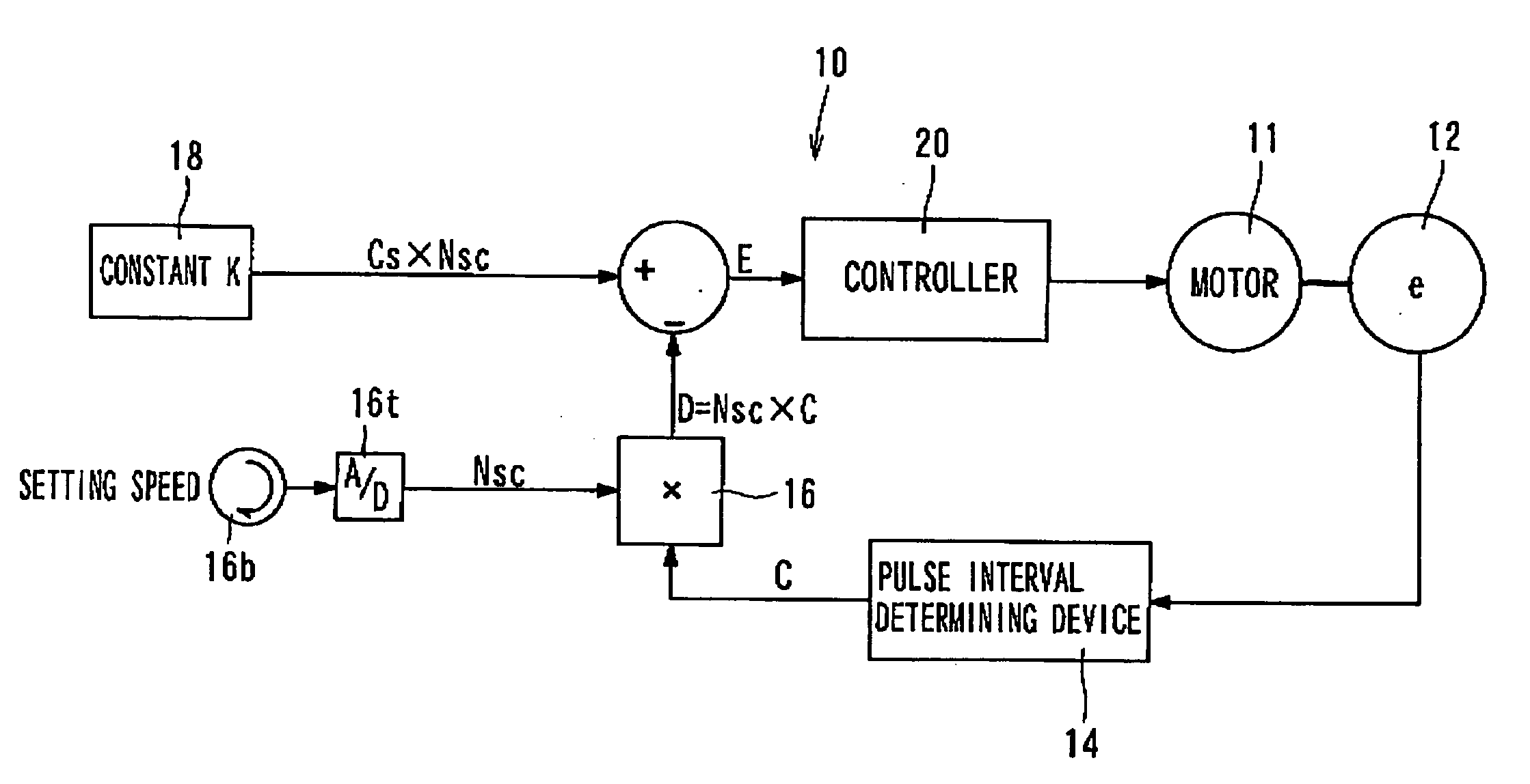
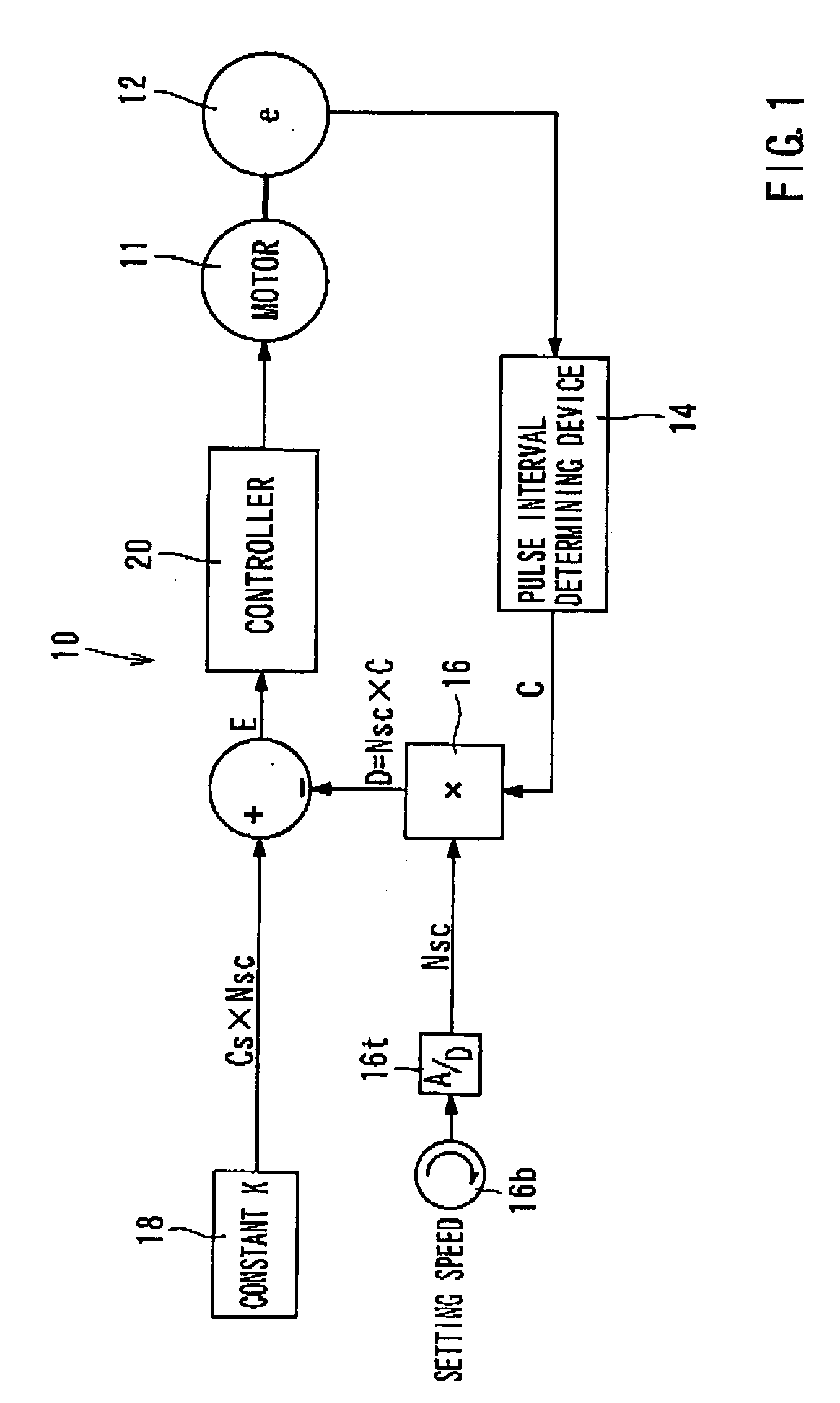
[0021]In this way, the comparative value changes with change of the speed change ratio but does not always change with the rotational speed of the motor. Thus, if the speed change ratio is the same, the comparative value will not be changed in either the case that the set rotational speed has been changed when the motor rotates at a low speed or the case that the set rotational speed has been changed when the motor rotates at a high speed. Thus, if the speed change ratio is the same, the difference between the comparative value and the set value is the same. Then, the controller adjusts the supply of power to the motor in order to decrease the difference.

Problems solved by technology

However, because the frequency / voltage converter 103 of the known system 100 converts a series of pulses into the voltage corresponding to the pulse density by means of the smoothing circuit, delay in transmission of signal may occur due to the smoothing circuit.
Therefore, it is necessary to provide additional circuit for compensating for the delay in phase caused by the smoothing circuit, resulting in increase of the cost of the control system 100.
In addition, even if the compensation has been made, it is likely that the usable speed range is limited.
Further, even if a small-bit low cost microcomputer (such as 8-bit to 16-bit microcomputers) is included for digitalizing the analogue value, it is difficult to obtain a voltage signal V in a desired accuracy from the smoothing circuit.
Therefore, it is not possible to properly accurately perform the control over the low speed operation and the high speed operation.

Method used


Image

  • Motor speed control systems
  • Motor speed control systems
  • Motor speed control systems

Examples


Embodiment Construction

[0036]Each of the additional features and teachings disclosed above and below may be utilized separately or in conjunction with other features and teachings to provide improved motor speed control systems. Representative examples of the present invention, which examples utilize many of these additional features and teachings both separately and in conjunction with one another, will now be described in detail with reference to the attached drawings. This detailed description is merely intended to teach a person of skill in the art further details for practicing preferred aspects of the present teachings and is not intended to limit the scope of the invention. Only the claims define the scope of the claimed invention. Therefore, combinations of features and steps disclosed in the following detailed description may not be necessary to practice the invention in the broadest sense, and are instead taught merely to particularly describe representative examples of the invention. Moreover, ...


PUM


Abstract

A motor speed control system includes a pulse outputting device capable of outputting a pulse each time a motor rotates, a pulse interval determining device capable of determining a pulse interval between the pulses outputted, and a comparative value calculating device capable of obtaining a comparative value as the product of a first value and a second value. The first value can correspond to the pulse interval determined, and the second value can correspond to a set rotational speed of the motor. The system can further include a set value calculating device capable of obtaining a set value as the product of the second value and a third value and a controller capable of controlling a supply of power to the motor such that a difference between the set value and the comparative value decreases.

Description

[0001]This application claims priority to Japanese patent application serial number 2006-70792, the contents of which are incorporated herein by reference.BACKGROUND OF THE INVENTION[0002]1. Field of the Invention[0003]The present invention relates to control systems for controlling motor speed.[0004]2. Description of the Related Art[0005]A known motor speed control system is shown in FIG. 7 and generally includes an encoder 102 for detecting the rotational speed of a motor 101, a frequency / voltage converter 103 for converting an output signal from the encoder 102 into a voltage signal V that represents the rotational speed, and a setting unit 104 that can output voltage signal Vs corresponding to a set value of the rotational speed.[0006]The encoder 102 is configured to output a pulse generation signal at each time that the motor 101 has rotated by a predetermined angle. The frequency / voltage converter 103 generates a pulse having a pulse width at each time that the pulse generatio...

Claims


Application Information

Patent Timeline
IPC IPC(8): H02P7/00H02P29/00
CPCH02P25/145
Inventor SAKO, MASAHIKONAGAI, MAYUMI
Owner MAKITA CORP
Why Eureka
Try Eureka