Temperature inversion detection and mitigation strategies to avoid compressor surge

Active Publication Date: 2021-08-19
HONEYWELL INT INC
View PDF0 Cites 0 Cited by
  • Summary
  • Abstract
  • Description
  • Claims
  • Application Information

AI Technical Summary

Benefits of technology

The patent describes a system and method for controlling the compressor inlet guide vanes of a gas turbine engine in an aircraft. The system includes an engine data source and an engine control unit. The engine control unit receives data from the engine data source and the inlet temperature value of the engine. The engine control unit processes the data to determine an inlet temperature modifier value, which is an estimate of the difference between the actual inlet temperature and the sensed inlet temperature. This modifier value is then added to the inlet temperature value to get a modified engine inlet temperature. The modified engine inlet temperature is then used in the compressor inlet guide vane control algorithm to control the compressor inlet guide vanes. The technical effect of this system is to improve the performance and efficiency of gas turbine engines in aircraft engines.

Problems solved by technology

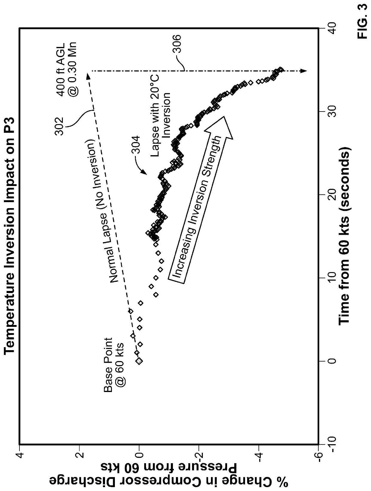
While the sensor lag and software delays are sufficient under normal operating conditions, this may result in insufficient response during temperature inversion events.
Thus, when taking off into a severe temperature inversion, or experiencing various other phenomenon that may result in an unexpected increase in engine inlet total temperature, the variable guide vanes may be miss-scheduled.
In some instances, this can cause the engine to surge.
An engine surge is undesirable because it can result in a thrust reduction.
If the thrust reduction is sufficient in magnitude and duration it can negatively affect the aircraft climb rate.

Method used


Image

  • Temperature inversion detection and mitigation strategies to avoid compressor surge
  • Temperature inversion detection and mitigation strategies to avoid compressor surge
  • Temperature inversion detection and mitigation strategies to avoid compressor surge

Examples


Embodiment Construction

[0019]The following detailed description is merely exemplary in nature and is not intended to limit the invention or the application and uses of the invention. As used herein, the word “exemplary” means “serving as an example, instance, or illustration.” Thus, any embodiment described herein as “exemplary” is not necessarily to be construed as preferred or advantageous over other embodiments. All of the embodiments described herein are exemplary embodiments provided to enable persons skilled in the art to make or use the invention and not to limit the scope of the invention which is defined by the claims. Furthermore, there is no intention to be bound by any expressed or implied theory presented in the preceding technical field, background, brief summary, or the following detailed description.

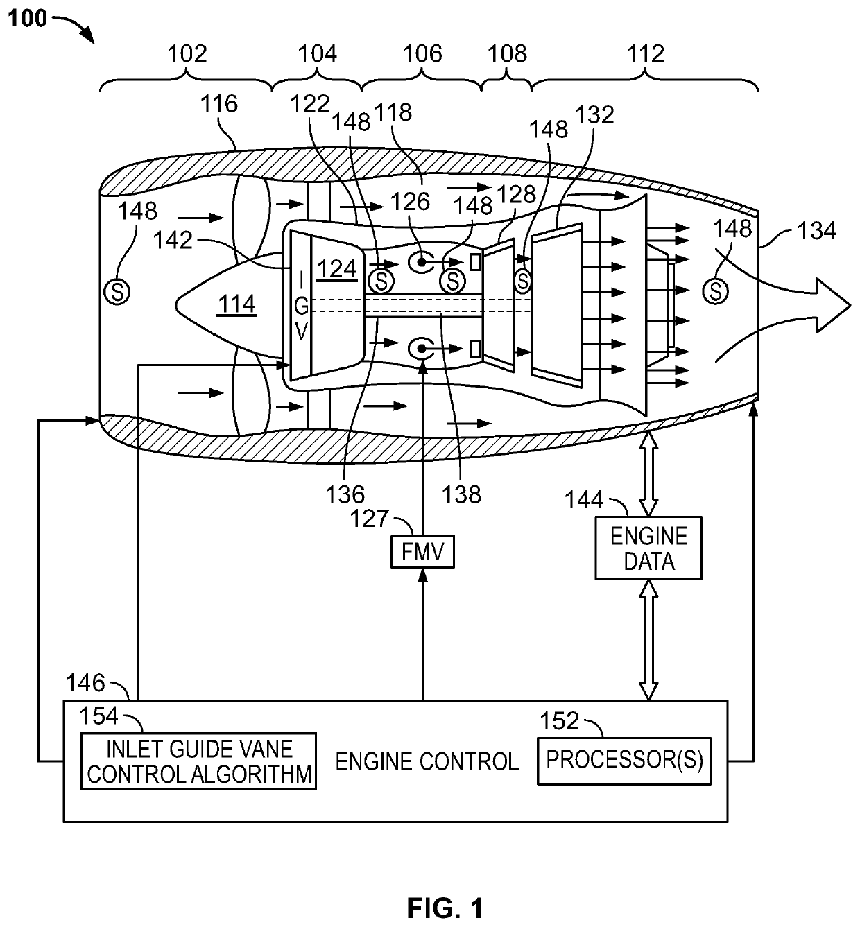
[0020]Turning now to FIG. 1, a functional block diagram of an exemplary gas turbine engine control system is depicted. The depicted system is for a dual-spool turbofan gas turbine engine 100. B...


PUM


Abstract

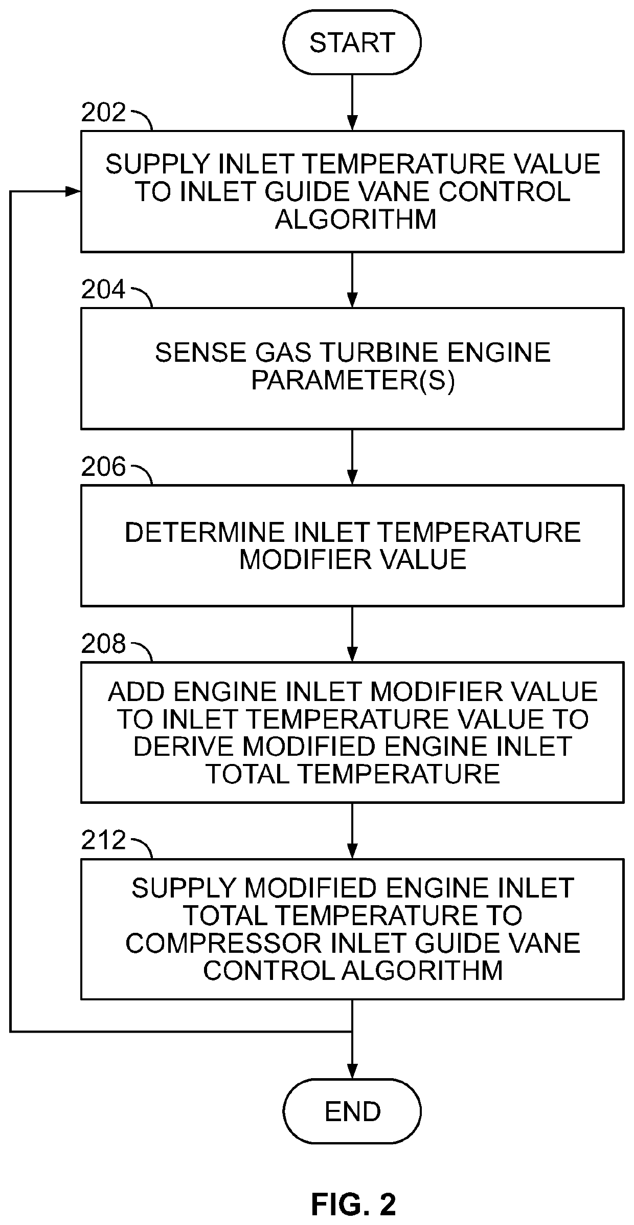
A system and method for controlling compressor inlet guide vanes of a gas turbine engine in an aircraft includes supplying, to a compressor inlet guide vane control algorithm, an inlet temperature value that is at least representative of sensed engine inlet total temperature. One or more gas turbine engine parameters are sensed with one or more sensors during operation of the gas turbine engine. The one or more gas turbine engine parameters are processed in the engine control unit to determine an inlet temperature modifier value that is an estimate of a difference between the sensed engine inlet total temperature and actual engine inlet total temperature. The inlet temperature modifier value is added to the inlet temperature value to derive a modified engine inlet total temperature. The modified engine inlet total temperature is used in the compressor inlet guide vane control algorithm, which controls the compressor inlet guide vanes.

Description

CROSS-REFERENCE TO RELATIVE APPLICATION[0001]This application claims priority to U.S. Provisional Patent Application No. 62 / 976,605, filed Feb. 14, 2020.TECHNICAL FIELD[0002]The present disclosure generally relates to gas turbine engines, and more particularly relates to systems and methods for controlling gas turbine engine compressor inlet guide vanes.BACKGROUND[0003]Commercial, business, and military aircraft are typically powered by gas turbine engines that have compression systems that employ variable guide vanes. The variable guide vanes on the compressor of a gas turbine engine are typically controlled as a function of various engine-related parameters, such as engine inlet temperature, pressure altitude, and compressor(s) rotational speeds. In many instances, engine inlet temperature is sensed using resistance temperature detectors (RTDs) or thermocouples, which are designed for high reliability and robustness, but can exhibit relatively long sensor lag. In addition, various...

Claims


Application Information

Patent Timeline
IPC IPC(8): F01D21/00F02C9/16
CPCF01D21/003F02C9/16F05D2220/323F05D2260/82F05D2270/101F05D2270/3032F05D2260/20F02C9/20F05D2270/303G01K13/028G01K7/42
Inventor HAUGLAND, RONNIECHAPMAN, GREGORY J.VHORA, MOHAMAD HANIFAITCHISON, JEFFREY J.
Owner HONEYWELL INT INC
Why Eureka
Try Eureka