Manufacturing method of head leading member

a manufacturing method and head technology, applied in the direction of typewriters, printing, power drive mechanisms, etc., can solve the problems of high cost of frame manufacturing by extrusion molding, difficult to directly cut mounting surfaces, difficult to materialize high accuracy, etc., to achieve the effect of easy forming, high degree of accuracy and inexpensively leading a head

Active Publication Date: 2021-08-19
MIMAKI ENG
View PDF0 Cites 0 Cited by
  • Summary
  • Abstract
  • Description
  • Claims
  • Application Information

AI Technical Summary

Benefits of technology

The patent describes a new way to create a head leading member for a printing machine that is cost-effective and can lead the printing machine's head with high accuracy. The method involves fixing a base member to a frame and ensuring that its guiding reference surface remains planar, so that the guide member can be placed accurately along a plane. This results in a reliable and efficient head leading member that can improve printing accuracy.

Problems solved by technology

Unfortunately, a frame manufactured by way of a cutting process for an extrusion-molded piece is costly.
On the other hand, in the case of a frame manufactured by way of a bending process on a metal plate, a certain level of accuracy could be secured by means of reforming a mounting surface for a guide member, while it is still difficult to directly cut the mounting surface in order to secure flatness, and therefore materializing high accuracy is difficult.

Method used


Image

  • Manufacturing method of head leading member
  • Manufacturing method of head leading member
  • Manufacturing method of head leading member

Examples


Embodiment Construction

[0044]A preferred embodiment with respect to a head leading member, a printing machine, and a manufacturing method of the head leading member according to the present disclosure is explained below with reference to the drawings. The present embodiment does not place any restriction on a scope of the present invention. Moreover, a constituent element in the embodiment described below includes any element with which a person skilled in the art can easily replace, and any element that is substantially the same as described below.

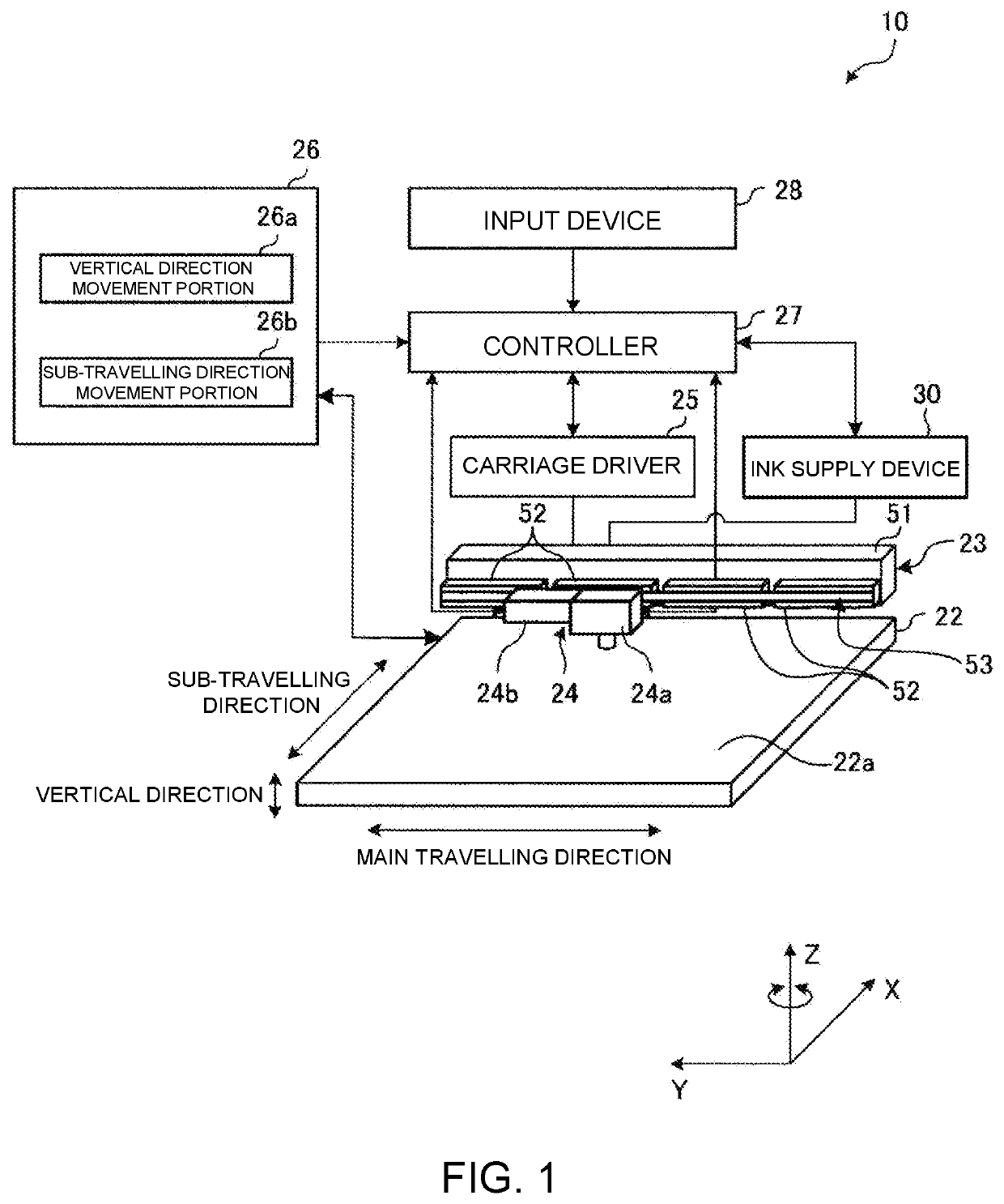
[0045]FIG. 1 is a schematic view drawing that shows a schematic configuration example of a printing machine 10 according to the present embodiment. In the present embodiment, an explanation is made with respect to an example in which a three-dimensional shaping device to shape, for example, a 3-dimensional shaped article is described. The printing machine 10 is not restricted to a three-dimensional shaping device, and may be another type of printing device, suc...


PUM


Abstract

A manufacturing method of a head leading member, which is provided in a printing machine including a head for discharging an ink toward a working surface, in order to lead the head in a main travelling direction, and the manufacturing method of a head leading member including: a base member fixing step in which a base member, being like a plate, is fixed to a frame extending in the main travelling direction; a guiding reference surface shaping step in which a surface of the base member, in a state of being fixed to the frame, is so manufactured as to be a plane, being along the main travelling direction, in such a way as to shape a guiding reference surface; and a guide member supporting step in which a guide member for leading the head is set in such a way that the guiding reference surface supports the guide member.

Description

CROSS REFERENCE TO RELATED APPLICATIONS[0001]This application is a divisional application of and claims the priority benefit of a prior application Ser. No. 16 / 547,552, filed on Aug. 21, 2019. The prior application Ser. No. 16 / 547,552 claims the priority benefit of Japanese Patent Application No. 2018-157052, filed on Aug. 24, 2018. The entirety of each of the above-mentioned patent applications is hereby incorporated by reference herein and made a part of this specification.TECHNICAL FIELD[0002]The present disclosure relates to a manufacturing method of a head leading member.DESCRIPTION OF THE BACKGROUND ART[0003]As a printing machine to carry out a printing operation for a medium, for example, there is known a printing machine of an ink-jet type, in which a liquid droplet is jetted out of a head onto a medium (for example, refer to Patent Document 1). Such a printing machine includes: for example, a placement table on which the medium can be placed; a head that jets out a liquid d...

Claims


Application Information

Patent Timeline
Patent Type & Authority Applications(United States)
IPC IPC(8): B41J25/304B41J11/00B41J2/21
CPCB41J25/304B41J2202/22B41J2/2103B41J11/005B41J3/28B41J19/00
Inventor KITAZAWA, TOSHIKI
Owner MIMAKI ENG
Why Eureka
Try Eureka