Display control apparatus, image capture apparatus, and methods for controlling the same
a control apparatus and image technology, applied in the field of display control apparatus and image capture apparatus, can solve the problem of difficult to easily recognize the quality of “bokeh” of captured images, and achieve the effect of easy recognition of “taste”
- Summary
- Abstract
- Description
- Claims
- Application Information
AI Technical Summary
Benefits of technology
Problems solved by technology
Method used
Image
Examples
first embodiment
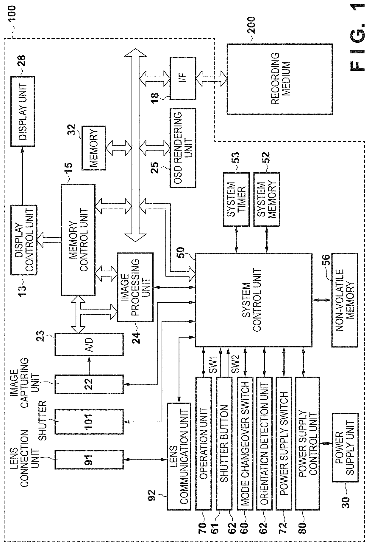
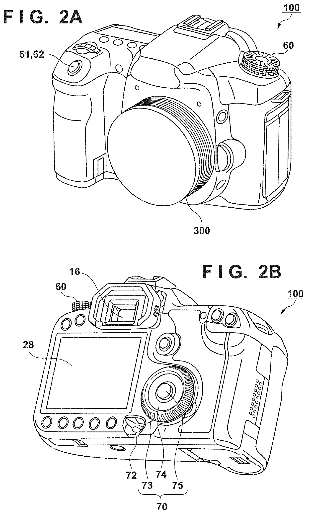
[0033]FIG. 1 is a block diagram illustrating an example of a functional configuration of a digital camera 100 (camera body) as an example of a display control apparatus according to the present embodiment. A shutter 101 is a focal plane shutter. An image capturing unit 22 is an image capturing element, in which a plurality of pixels are positioned two-dimensionally, for converting an optical image into a group of analog electrical signals and may be a CCD or a CMOS image sensor.
[0034]An A / D conversion unit 23 converts a group of analog electrical signals outputted from the image capturing unit 22 into a group of digital signals (image data). The A / D conversion unit 23 may be included in the image capturing unit 22.
[0035]An image processing unit 24, by applying preset image processing in relation to the image data supplied from the A / D conversion unit 23 or a memory control unit 15, generates signals and image data and acquires and / or generates various information. An image processin...
second embodiment
[0090]Next, a second embodiment will be described. In the first embodiment, an index based on the amount of variance A in the T-number was used as an index for indicating smoothness of blurred images. However, another index may be used. The present embodiment may be the same as the first embodiment except for the bokeh index and the method for presenting the bokeh index item 430, and therefore description regarding a configuration and an operation of an apparatus common to those of the first embodiment will be omitted.
[0091]FIG. 8A is a view illustrating an example of a relationship between Δ / ΔMAX and a normalized transmittance modulation amount. The normalized transmittance modulation amount includes values from 0 to 1 and is a value in which light transmittance according to a magnitude (radius r) of a pupil region of an image capturing optical system was normalized by light transmittance of when a magnitude of the pupil region is the greatest (radius r0).
[0092]As illustrated in FI...
third embodiment
[0104]Next, a third embodiment will be described. The present embodiment may be the same as the first embodiment except for the method for presenting the bokeh index item 430, and therefore description regarding a configuration and an operation of an apparatus common to those of the first embodiment will be omitted.
[0105]FIG. 9A to FIG. 9C are views schematically illustrating control for displaying the bokeh index item 430 in the embodiment. Configurations that are the same as in FIG. 6 will be given the same reference numerals and redundant descriptions are omitted. Also, FIG. 10 is a flowchart relating to an operation for controlling a display of the bokeh index item 430 in the present embodiment. An operation that is indicated in the flowchart in FIG. 10 is realized by a program that is stored in the non-volatile memory 56 being deployed in the system memory 52 and then executed by the system control unit 50. Note that this processing can be executed as part of an operation for a...
PUM
 Abstract
Description
Claims
Application Information
 - R&D
- Intellectual Property
- Life Sciences
- Materials
- Tech Scout
- Unparalleled Data Quality
- Higher Quality Content
- 60% Fewer Hallucinations
Browse by: Latest US Patents, China's latest patents, Technical Efficacy Thesaurus, Application Domain, Technology Topic, Popular Technical Reports.
© 2025 PatSnap. All rights reserved.Legal|Privacy policy|Modern Slavery Act Transparency Statement|Sitemap|About US| Contact US: help@patsnap.com


