Wireless Power Transfer Method and System Using the Same

a power transfer system and wireless technology, applied in the direction of transformers, electrical equipment, inductances, etc., can solve the problems of unsolved instability of the system, waste to the other eigenmode, and the likely serious damage to the complex components and systems of the system, so as to achieve efficient and stable power transfer, improve stability, and simple operation

Inactive Publication Date: 2021-08-12
TONGJI UNIV
View PDF0 Cites 0 Cited by
  • Summary
  • Abstract
  • Description
  • Claims
  • Application Information

AI Technical Summary

Benefits of technology

[0006]In view of the above-mentioned problems, the invention provides a wireless power transfer system and method. The wireless power transfer system mainly comprises a signal source, an exciting coil, a pair of resonance coils having the same resonance frequency, a receiving coil and a load. The resonance frequency is regulated by the pair of resonance coils formed by winding litz wires on side faces of organic glass plates and by loading capacitors, and the working frequency is made close to the resonance frequency of the resonance coils by means of the physical properties of a single-mode point in a non-Hermitian system, so as to regulate the energy transfer rate out of the system by controlling the distance between the receiving coil and the adjacent resonance coil. With such a design, it is ensured that the system is located at the single-mode point while the coupling distance between the pair of resonance coils is changed, the technical defects of the prior art are overcome, and effective wireless power transfer and mono-frequency efficient wireless power transfer within the KHz frequency range are realized by means of the physical properties of fixed frequency and minimum loss at the single-mode point.
[0023]By adoption of the above technical scheme, the invention has the following beneficial effects:
[0025](2) The exciting coil, the receiving coil and the two resonance coils in the dual resonance coil device support power transfer over 100 watts, and the system is free from complicated and complex circuit elements, thereby having better stability than traditional solutions when operating at high power.
[0026](3) When the coupling distance between the resonance coils is changed, the wireless power transfer system can still track the single-mode point by adjusting the distance between the receiving coil and the corresponding resonance coil, thereby having the effects of simple operation, efficient and stable power transfer.

Problems solved by technology

However, by adoption of this method, modulation to and feedback from both the exciting terminal and the receiving terminal are required, and complicated components and systems are likely to be seriously damaged and even burnt out when operating under high power.
Even this scheme can realize effective power transfer within a certain distance, the instability of the system is still left unsolved due to the complexity of circuit elements under high power.
In addition, this system has two real eigenmodes and an extra effective gain, but only one eigenmode is used for power transfer, which leads to a waste to the other eigenmode.
According to such a design, not only an existing element is wasted, additional power consumption is consumed as well.
In sum, using non-radiative magnetic-field coupling coils to undergo wireless power transfer seems to be a trend in this field, however, the reduction of transfer efficiency caused by near-field coupling mode splitting is still a problem yet to be solved.
For the time being, there is still no effective solution capable of ensuring stable system working frequency and efficiency under the consideration of the variations of transfer distance.

Method used


Image

  • Wireless Power Transfer Method and System Using the Same
  • Wireless Power Transfer Method and System Using the Same
  • Wireless Power Transfer Method and System Using the Same

Examples


embodiment 1

[0049]In this embodiment, a wireless power transfer system comprising a dual resonance coil device is provided.

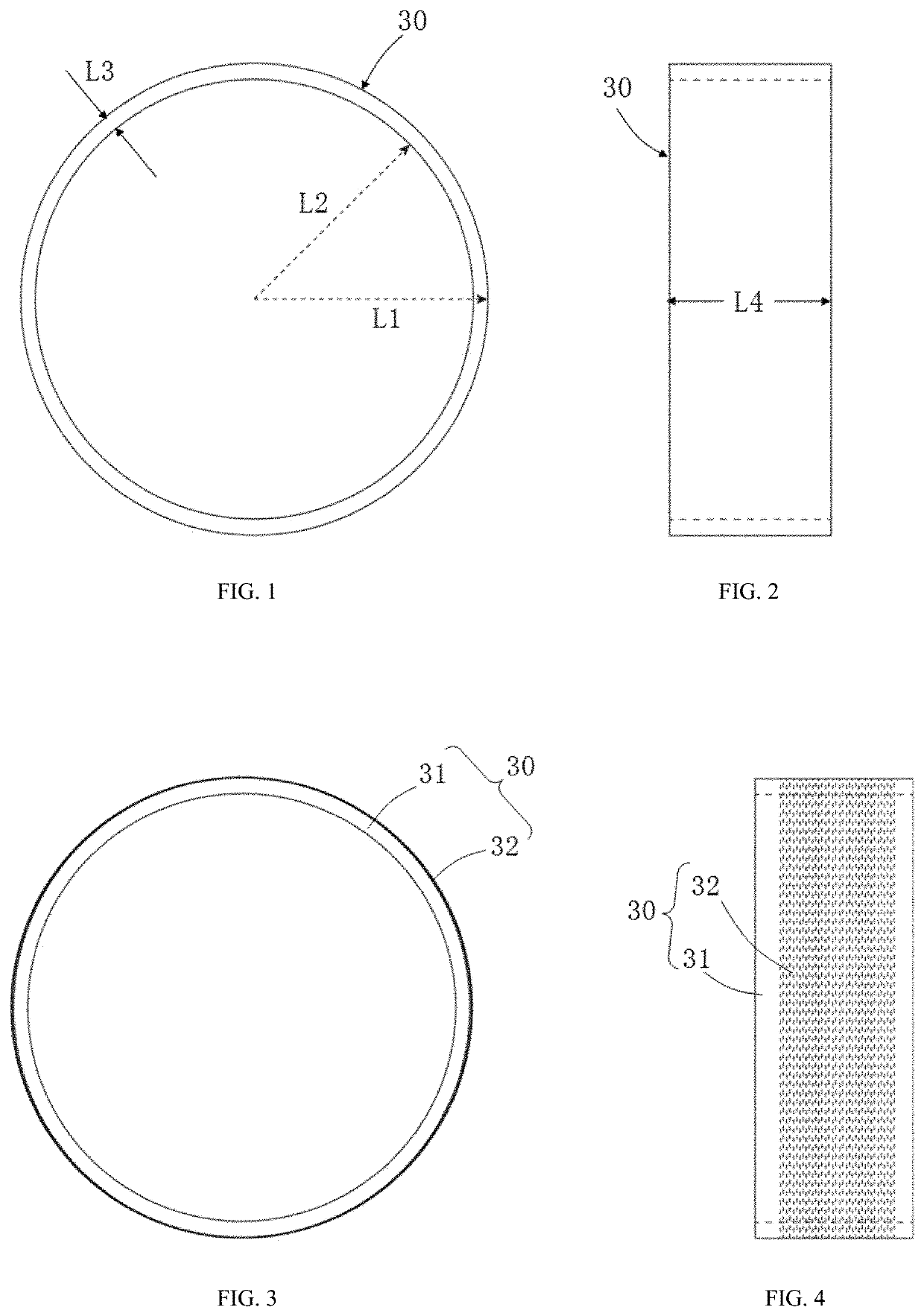
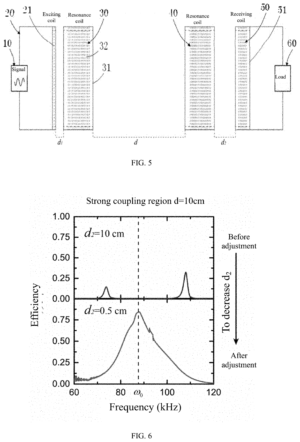
[0050]The wireless power transfer system can be used for wireless power transfer for high-power electric automobiles under a working frequency of 85 KHz and comprises a signal source 10, an exciting coil 20, a pair of coils having a resonance frequency of 85 kHz (a first resonance coil 30 and a second resonance coil 40), a receiving coil 50 and a load 60. Each resonance coil is formed by an organic glass plate (insulating dielectric plate), a litz wire (metal wire) closely wound on the organic glass plate by 22 turns and capacitors (lumped parameter elements) welded to the litz wire.

[0051]The resonance coil is prepared through the following steps:

[0052]The litz wire is closely wound on a side face of the organic glass plate by 22 turns, and then the capacitors are connected to the head end and the tail end of the litz wire.

[0053]The structure of the organic glass plate in t...

embodiment 2

[0056]In this embodiment, an operation method of the wireless power transfer system in embodiment 1 is provided.

[0057]FIG. 5 shows the high-power efficient wireless power transfer system applicable to a working frequency of 85 kHz. As shown in FIG. 5, after a signal at the eigenfrequency is made to enter the exciting coil via the signal source, the first resonance coil is excited. Afterwards, power is transmitted to the second resonance coil through near-field magnetic coupling. Finally, the power is coupled out via the receiving coil to be received by the load, wherein d1, d and d2 separately refer to the distance between the exciting coil and the first resonance coil, the distance between the resonance coils and the distance between the second resonance coil and the receiving coil.

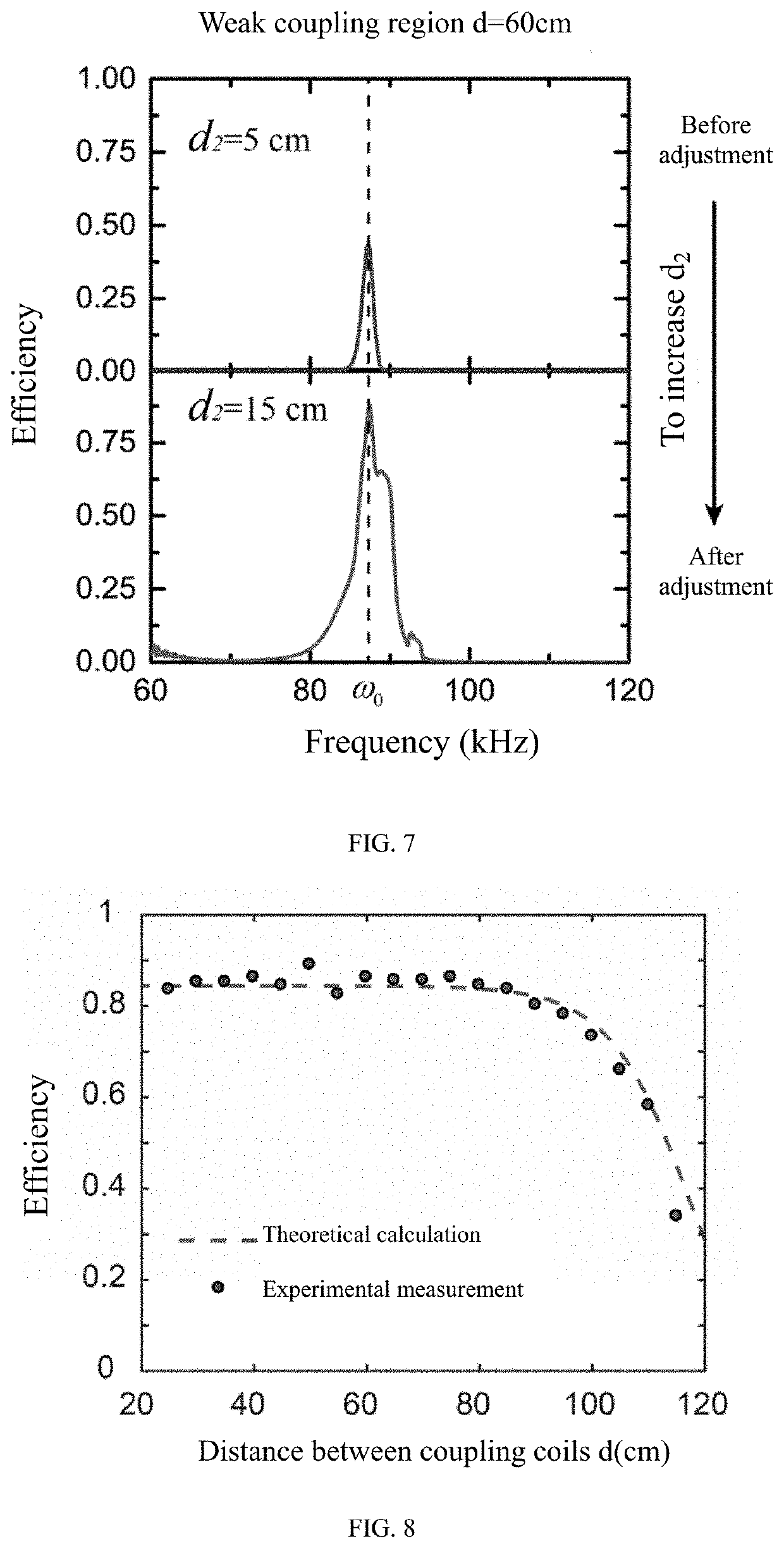
[0058]FIG. 6 is an efficiency comparison diagram before and after the system in embodiment 1 is adjusted to a single-mode point in by regulating the coupling distance d into a strong coupling region, and...


PUM


Abstract

A wireless power transfer system has a signal source, an exciting coil, a pair of resonance coils having the same resonance frequency, a receiving coil and a load. The resonance frequency is regulated by the pair of resonance coils. The working frequency is made close to the resonance frequency of the resonance coils by means of the physical properties of a single-mode point in a non-Hermitian system, so as to regulate the energy transfer rate by controlling the distance between the receiving coil and the adjacent resonance coil. The system is located at the single-mode point while the coupling distance between the pair of resonance coils is changed and efficient wireless power transfer and mono-frequency efficient wireless power transfer within the kHz frequency range are realized by means of the physical properties of fixed frequency and minimum loss at the single-mode point.

Description

BACKGROUND OF THE INVENTION1. Technical Field[0001]The invention relates to the technical field of wireless power transfer, in particular to a wireless power transfer system and method using non-radiative magnetic-field coupling coils.2. Description of Related Art[0002]Wireless power transfer (WPT) is to transform electricity power to another form of intermediate energy such as electromagnetic field energy, lasers, microwaves and mechanical waves by a transmitter and then the intermediate energy is converted by receivers into electricity power again after being transferred in air for a certain distance. In terms of different forms of the intermediate energy in the electricity power transfer process, there are wireless power transfer of a magnetic-field coupling type, wireless power transfer of an electric field coupling type, wireless power transfer of an electromagnetic radiation type and wireless power transfer of a mechanical wave coupling (ultrasonic wave coupling) type. Due to ...

Claims


Application Information

Patent Timeline
Patent Type & Authority Applications(United States)
IPC IPC(8): H02J50/90H02J50/12
CPCH02J50/90H02J50/12H01F38/14
Inventor LI, YUNHUIZHU, KEJIAZENG, CHAOJIANG, JUNSUN, YONGFANG, KAICHEN, YUGUANGZHANG, YEWENCHEN, HONG
Owner TONGJI UNIV
Why Eureka
Try Eureka