
Method for calculating kinetic parameters of a reaction network

a reaction network and kinetic parameter technology, applied in the field of methods for calculating kinetic parameters of a reaction network, can solve the problems of affecting the workflow of evaluating an observed signal, affecting the accuracy of the observed signal,

Pending Publication Date: 2021-08-05
CREOPTIX
View PDF0 Cites 0 Cited by
  • Summary
  • Abstract
  • Description
  • Claims
  • Application Information

AI Technical Summary

Benefits of technology

The patent text describes a new method for estimating reaction networks' kinetic parameters. Previous methods were slow and could only be used for simulations, whereas the new method can be applied to real-life situations. It is faster and more accurate, allowing for advanced statistical analysis and model selection. The method can efficiently calculate kinetic parameters from an observed signal or sequence of signals.

Problems solved by technology

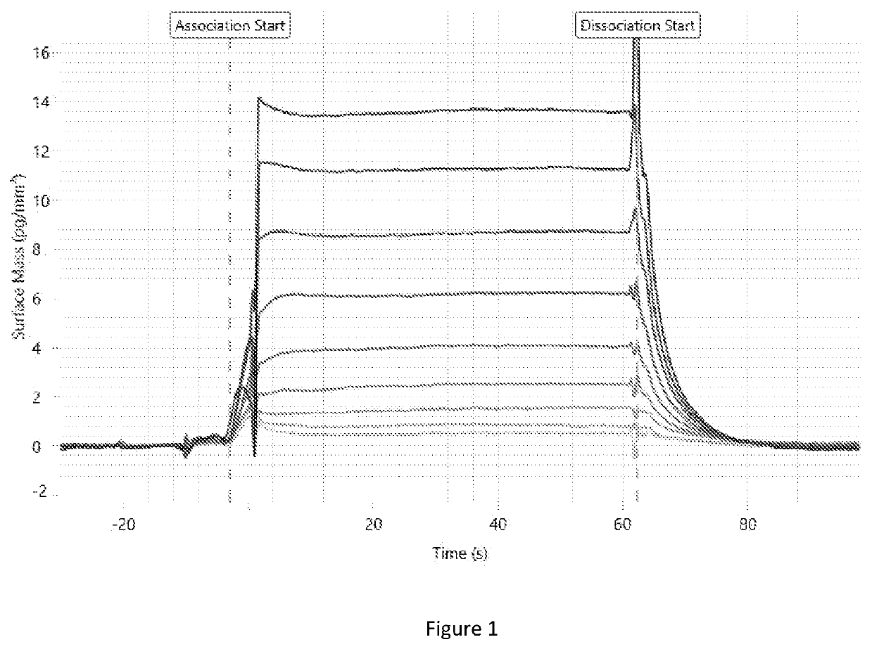
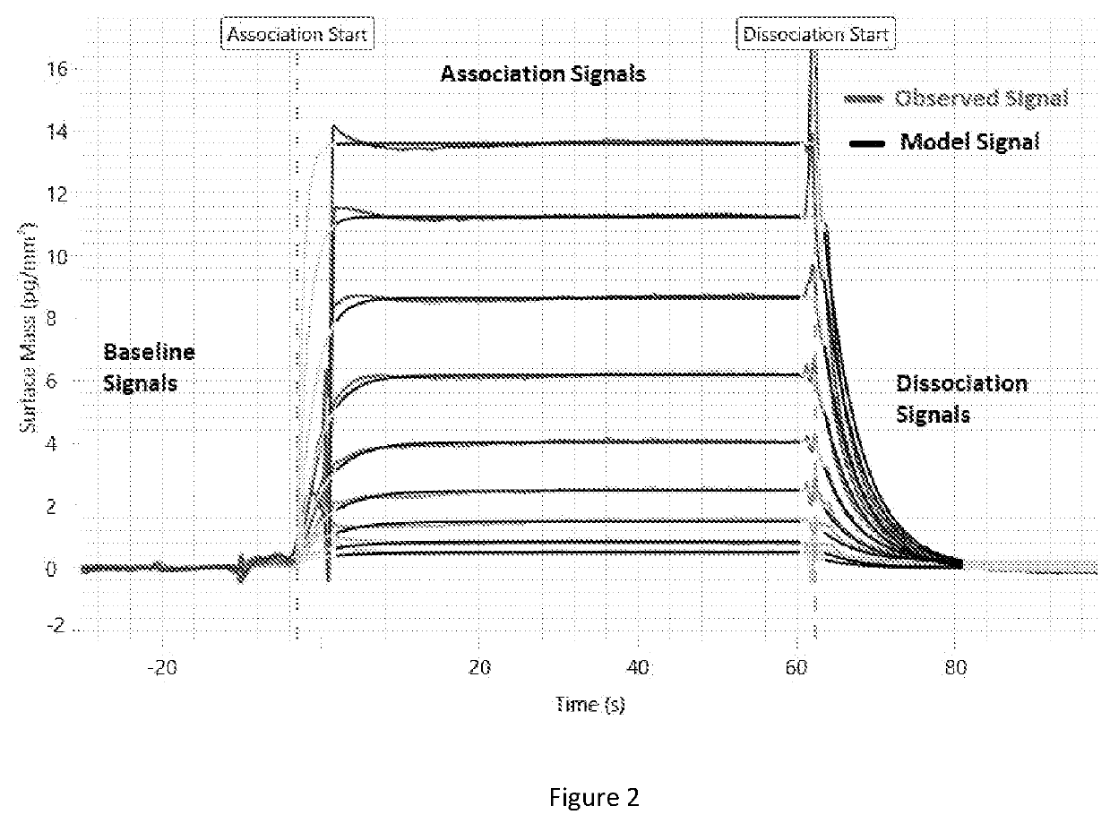
An acquisition method typically has physical limitations and the acquired signal contains noise and artefacts resulting from these physical limitations of the acquisition method.
The repeated solving of the reaction network model, including necessary numerical integrations, is computationally intensive and delays the workflow of evaluating an observed signal.
In particular, the workflow becomes inconveniently long when repeated evaluation is needed to tune the fit.
Further on, computing the estimation errors of the obtained values for the kinetic parameters is a complex problem (Johnson, Simpson, & Blom, 2009), which needs repeated fitting and becomes unfeasible on a single processor.
The major drawback of iterative minimization methods, in particular when the model requires numerical integration, is the significant computation time required to achieve convergence.
The computation time introduces significant delays in the experimenters' workflow who is unable to quickly evaluate the kinetic parameters for different configurations.
Further on, the computational complexity of iterative methods prevents real time Monte-Carlo simulations to compute the estimation error, tune hyperparameters such as the fit range, or perform model selection.
However, a major drawback of the method is that it remains iterative and the determined kinetic parameters are only an approximation whose precision depends on how well the functional basis approximates the true solution of the differential equation.
Besides the limitation of direct estimation methods to observed signals that observe all states in a reaction network, the statistical properties of current direct estimation methods are not always optimal.
An undesirable statistical feature that can arise in iterative methods and direct estimation methods are biases in the determined kinetic parameters.
A bias arises when the expected value of a result differs from the true underlying quantitative value being estimated.
Biases are difficult to correct because they require knowledge of the distribution underlying discrepancies between the observed signal and the model signal.
For Gaussian independent noise in the observed signal, direct estimation methods are known to be more prone to biases and have lower statistical efficiency than iterative methods.
Nonetheless, the statistical properties of direct estimation methods remain unknown for dependent observation errors and heavy-tailed observation errors, which are common in applications.
In summary, state-of-the-art iterative methods which are used to determine kinetic parameters of a reaction network are insufficient because they are computationally intensive and delay the workflow of evaluating observed signals.
State-of-the-art direct estimation methods which are used to determine kinetic parameters of a reaction network are insufficient because they cannot be applied to observed signals that do not observe all states of a reaction network.
The recent development of a direct estimation methods that applies to reaction networks with hidden states (Dattner, 2015) relies on a parametric functional approximation of the hidden states that is optimized using iterative methods; however disadvantageously this approach results only in an approximation and requires case by case educated guesses for the choice of the functional basis.

Method used


Image

  • Method for calculating kinetic parameters of a reaction network
  • Method for calculating kinetic parameters of a reaction network

Examples


example 1

Reaction Network

[0126]Assume a reversible reaction between an analyte A and a surface-bound (immobilized) capturing molecule, or ligand, B which is not diffusion or mass transfer limited and obeys pseudo first order kinetics:

A+BAB.  (36.)

[0127]The state of this reaction network is given by

{xo(t),xh(t)}=([A],[AB])@([B]),  (37.)

where the concentrations of the analyte A and the product AB are the observed state, and the concentration of the ligand B is the hidden state.

[0128]The differential equations determining the reaction network state over time are

[{dot over (A)}]=0,  (a)

[{dot over (B)}]=−ka[A][B]+kd[AB],  (b)

[]=ka[A][B]−kd[AB],  (c) (38.)

where the analyte concentration [A] is a known constant.

[0129]Then the integrated form of Equation (38.b) and Equation (38.c) are used to eliminate the ligand concentration as

[{dot over (B)}]=−[]⇒→[B]=R−[AB],  (39.)

where R is an ‘integration constant’, namely the initial ligand concentration.

[0130]The elimination steps yield the intermediate diff...

example 2

Reaction Network with an Observed Signal Offset

[0146]An observed signal can contain an observed signal offset, which is an offset constant in time by which the observed signal differs from the model signal. Observed signal offsets are particular common in observed signals which have been obtained by performing an acquisition method using a label-free sensor. In this case, to reliably estimate the kinetic parameters of the reaction network, the observed signal offset needs to be jointly determined with the kinetic parameters. The following embodiment uses a direct estimation method that determines jointly the kinetic parameters and the observed signal offset.

[0147]In such an embodiment the discrepancy function is

[]−ka[A](R−e−[AB])+kd[AB]+kd·e=0,  (53.)

wherein e is an observed signal offset to the observed signal as [AB]→[AB]+e in Equation (40.), and which is overparametrized by R and e that are exchangeable degrees of freedom.

[0148]The estimation of the parameters ka, kd, R and e is ...

example 3

ady State Mass Transport Reaction Network

[0166]Common observed signals a represented by reaction networks involving an analyte diffusing to a surface and then reacting with a ligand immobilized at the surface, reaction which is described by the reaction network

AAs+BAsB.  (64.)

Hereafter, [As] is the surface analyte concentration, the concentration of the analyte at the surface where the ligand is immobilized. When the diffusion of the analyte to the surface is slow, the surface analyte concentration becomes time dependent and differs from the fixed analyte concentration [A], reason the surface analyte concentration needs to be modelled.

[0167]The state of this reaction network is described by

{xo(t),xh(t)}([A],[AsB])@([As],[B]),  (65.)

where the concentrations of the analyte and the complex are observed states, and the concentrations of the surface analyte and ligand are hidden states.

[0168]The differential equations determining the time evolution of the reaction network state over time...


PUM


Abstract

According to the present invention there is provided a method of calculating kinetic parameters of a reaction network, the method comprising the steps of: providing an intermediate objective function, wherein said intermediate objective function comprises a linearized intermediate discrepancy function which comprises intermediate parameters which have been determined by applying a reparameterization function to the parameters of the discrepancy function, wherein the intermediate discrepancy function is linear with respect to all of said intermediate parameters; determining values for each of the intermediate parameters in said linearized intermediate discrepancy function, which minimize the intermediate objective function, using a direct estimation method; determining values for the parameters of the discrepancy function by applying an inverse of the reparameterization function to said determined values of the intermediate parameters; determining values for the kinetic parameters from said determined values for said parameters of the discrepancy function. There is further provided a tangible data carrier comprising program code arranged for causing a processor to carry out said method.

Description

FIELD OF THE INVENTION[0001]The present invention concerns methods for calculating kinetic parameters of a reaction network which involves providing an intermediate objective function which comprises a linearized intermediate discrepancy function, wherein all hidden states have been eliminated, and minimizing the intermediate objective function, using a direct estimation method.DESCRIPTION OF RELATED ART[0002]A chemical or biochemical reaction network describes the reactions, in general reversible, occurring between a set of reactants to form a set of products, wherein a reactant is a substance that takes part in and undergoes change during a reaction and a product is a substance that is the result of a reaction between one or more reactants. A reactant can simultaneously be a product and a product can simultaneously be a reactant in a reaction network.[0003]The state of a reaction network is given by the set of concentrations of all reactants and products in the reaction network, o...

Claims


Application Information

Patent Timeline
Patent Type & Authority Applications(United States)
IPC IPC(8): G16B5/30G16B45/00G06F17/13G06F17/17
CPCG16B5/30G06F17/17G06F17/13G16B45/00G16B5/00G16C20/10
Inventor COTTIER, KASPARFIEVET, LUCAS
Owner CREOPTIX
Learn More