Blow-off valve with dual axis internal seal ring

a technology of internal seals and blow-off valves, which is applied in the direction of valve operating means/release devices, machines/engines, mechanical equipment, etc., can solve the problems of increasing the ratio of fuel in the fuel/air mixture supplied to the engine, and affecting the operation of the valve. , to achieve the effect of reducing the number of child parts and avoiding internal leakag

Inactive Publication Date: 2021-08-05
PADMINI VNA MECHATRONICS PVT LTD
View PDF0 Cites 2 Cited by
  • Summary
  • Abstract
  • Description
  • Claims
  • Application Information

AI Technical Summary

Benefits of technology

The present invention provides a blow-off valve for an internal combustion engine with a dual axis internal seal ring that works in both axial and radial directions to improve leakage and reduce assembly parts. The plunger body is designed to assemble into the moving core without any additional attachments and is secured inside a plunger housing with a compression spring using the dual axis internal seal ring. The valve has improved design complexity and low manufacturing cost. The dual axis internal seal ring remains fix in its position and allows for lower opening and closing time of the valve and has less chances of wear and tear. Overall, the invention reduces child parts of assembly and assists in improving design complexity and lowering manufacturing costs.

Problems solved by technology

When the throttle of such an engine closes during operation, certain detrimental effects can result.
These include a build-up of pressure downstream of the throttle with a resultant undesirable increase in heat, a rapid deceleration of the supercharger compressor with a resultant increase in potentially damaging or wearing forces on the compressor, excessive and unpleasant noise effects, and an increase in the ratio of fuel in the fuel / air mixture supplied to the engine which results in the engine running rich.
All these requirements of extreme operating conditions lead to expensiveness especially of the actuation of the blow-off valve.
The drawback associate to invention is that, it is very complex in design and consecutively costly due to large number of components.
Again, it is very complex in design and consecutively costly due to large number of components.
Being a complex designed assembly and large number of components, the valve will be costly to produce and needs more accuracy check while being assembled.

Method used


Image

  • Blow-off valve with dual axis internal seal ring
  • Blow-off valve with dual axis internal seal ring
  • Blow-off valve with dual axis internal seal ring

Examples


Embodiment Construction

[0021]The present invention will now be described more fully hereinafter with reference to the accompanying drawings in which a preferred embodiment of the invention is shown.

[0022]This invention may, however, be embodied in many different forms and should not be construed as being limited to the embodiment set forth herein. Rather, the embodiment is provided so that this disclosure will be thorough, and will fully convey the scope of the invention to those skilled in the art.

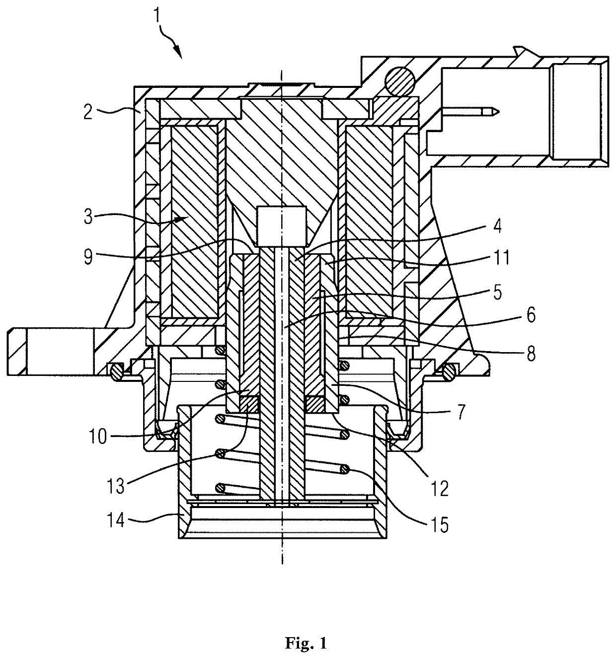
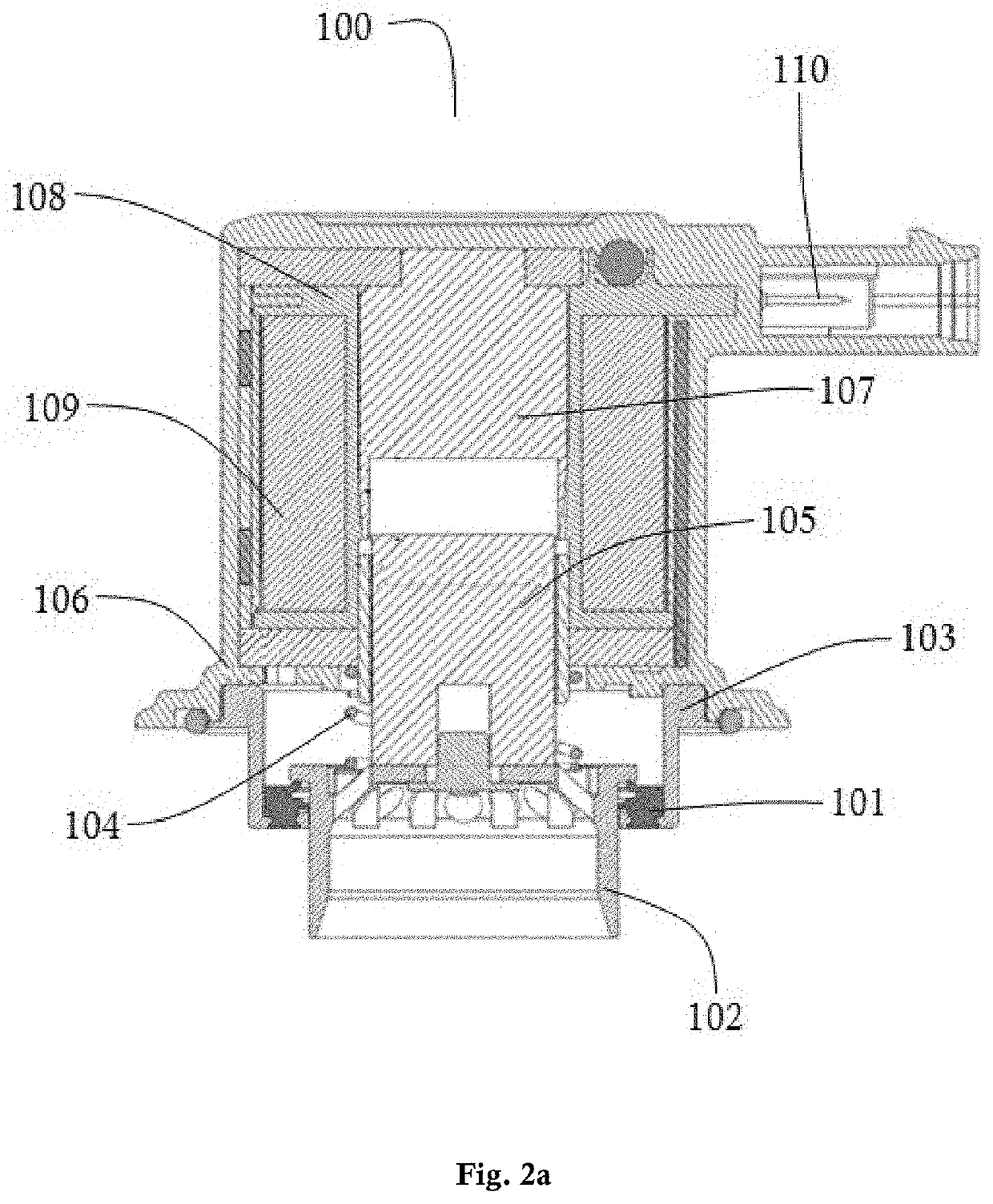
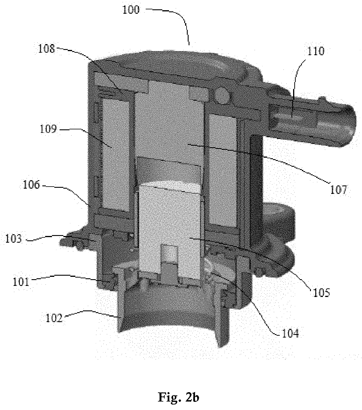
[0023]In a most preferred embodiment, the present invention provides a blow off valve with improved internal leakage comprising of: a plunger body, a compression spring, a moving core, a two axis internal seal ring, a fix core, a bobbin, a metallic coil, a coil housing, a plunger housing and a plurality of terminal pins; wherein, the two axis internal seal ring remains fixed co-axially between the plunger housing and the plunger body; the two axis internal seal ring is having two lips for sealing internal leaka...


PUM


Abstract

The present invention provides a blow-off valve for an internal combustion engine. More specifically, the invention provides a blow-off valve with dual axis internal seal ring that works in axial and radial direction to improve the leakage while reducing the child parts of assembly. The blow-off valve provided comprises of a plunger body, a compression spring, a moving core, a two axis internal seal ring, a fix core, a bobbin, coil, coil housing, a plunger housing and terminals to power up the coil.

Description

FIELD OF THE INVENTION[0001]The present invention provides a blow-off valve for an internal combustion engine. More specifically, the invention provides a blow-off valve with dual axis internal seal ring that works in axial and radial direction to improve the leakage while reducing the child parts of assembly.BACKGROUND OF THE INVENTION[0002]Superchargers are utilized in internal combustion engines to increase volumetric efficiency of the engines and thereby to enhance the performance of the engines. When the throttle of such an engine closes during operation, certain detrimental effects can result. These include a build-up of pressure downstream of the throttle with a resultant undesirable increase in heat, a rapid deceleration of the supercharger compressor with a resultant increase in potentially damaging or wearing forces on the compressor, excessive and unpleasant noise effects, and an increase in the ratio of fuel in the fuel / air mixture supplied to the engine which results in...

Claims


Application Information

Patent Timeline
IPC IPC(8): F16K31/06F02B37/16
CPCF16K31/0655F16K31/0693F02B37/16F16K1/42Y02T10/12
Inventor BHANDARI, KABIRKUMAR, AMARDIPABHISHEK, KUMARROUT, PARSURAM
Owner PADMINI VNA MECHATRONICS PVT LTD
Why Eureka
Try Eureka