Steel reinforced concrete column

a technology of reinforced concrete and steel, applied in the direction of building reinforcements, constructions, building components, etc., can solve the problems of general efficiency, and achieve the effect of improving notably the quality of the column and being easy to build

Active Publication Date: 2021-07-29
ARCELORMITTAL INVESTIGACION Y DESARROLLO SL
View PDF0 Cites 0 Cited by
  • Summary
  • Abstract
  • Description
  • Claims
  • Application Information

AI Technical Summary

Benefits of technology

[0028]The outer reinforcement cage advantageously comprises multitude of closed circular rebar rings connected to the longitudinal rebars. It will be appreciated that these closed circular rebar rings efficiently oppose a transversal pressure generated in the axially compressed concrete, by being capable of absorbing important circumferential tension stresses (similar to a cylindrical wall of a pressure vessel).
[0029]The concrete may also advantageously comprise an inner reinforcement cage formed of longitudinal and transversal rebars, which is arranged between the outer flanges and the inward flanges so as to enclose the central concrete core. This inner concrete reinforcement cage provides in particular a confinement of an intermediate concrete layer immediately surrounding the central concrete core. It thereby opposes a transversal pressure generated in this intermediate concrete layer under axial compression forces, so that this intermediate concrete layer may contribute up to higher loads to the bearing capacity of the steel reinforced concrete column.
[0030]The inner reinforcement cage preferably comprises closed circular rebar rings passing through holes in the webs of the steel sections. It follows that these rings are structurally independent from the arrangement of steel sections, which is of advantage when the steel sections are exposed to deformations. Alternatively, the inner reinforcement cage comprises arc-shaped segments of rebar rings welded with their ends to the webs of the steel sections. While being less advantageous from the structural point of view, this alternative embodiment has however the non-negligible advantage that it is not necessary to drill holes into the webs of the steel sections.
[0031]In a preferred embodiment, the steel reinforced concrete column comprises at least two longitudinally spaced beam-to-column connection nodes. Such a “beam-to-column connection node” is a specific section of the steel reinforced concrete column that is specifically equipped for connecting thereto load bearing beams supporting for example a floor in a high rise building. It will be appreciated that between two successive beam-to-column connection nodes, there is advantageously no structural steel interconnecting the steel sections. In other words, between two successive beam-to-column connection nodes, the bearing steel structure of the steel reinforced concrete column just consists of isolated steel sections extending in parallel through the column. At the beam-to-column connection nodes, the steel sections may however be structurally interconnected by means of structural steel. The term “structural steel” herein designates a variety of heavy steel shapes, such as H-beams, I-beams, T-beams, heavy U- or L-sections and heavy steel plates, used as load bearing or load transferring members in a steel structure. Rebars are, in this context, not considered as structural steel. Thanks to the absence of structural steel interconnecting the steel sections between two successive beam-to-column connection nodes, onsite welding work on structural steel is strongly limited which improves notably the quality of the column and makes the latter easier to build.

Problems solved by technology

However, building such a steel skeleton generally requires a lot of onsite welding work on heavy structural steel, which is costly, time consuming and may result in quality problems.
Steel reinforced concrete columns of this second type do not require a lot of onsite welding work on heavy structural steel, but they are generally less efficient as regards the cooperation between the concrete and the steel sections for warranting a high bearing capacity.

Method used


Image

  • Steel reinforced concrete column
  • Steel reinforced concrete column
  • Steel reinforced concrete column

Examples


Embodiment Construction

[0052]It will be understood that the following description and drawings describe embodiments of the invention by way of example and for illustration purposes. They shall not limit the scope, nature or spirit of the claimed subject matter. In the drawings, equivalent elements in different embodiments bear the same reference numbers.

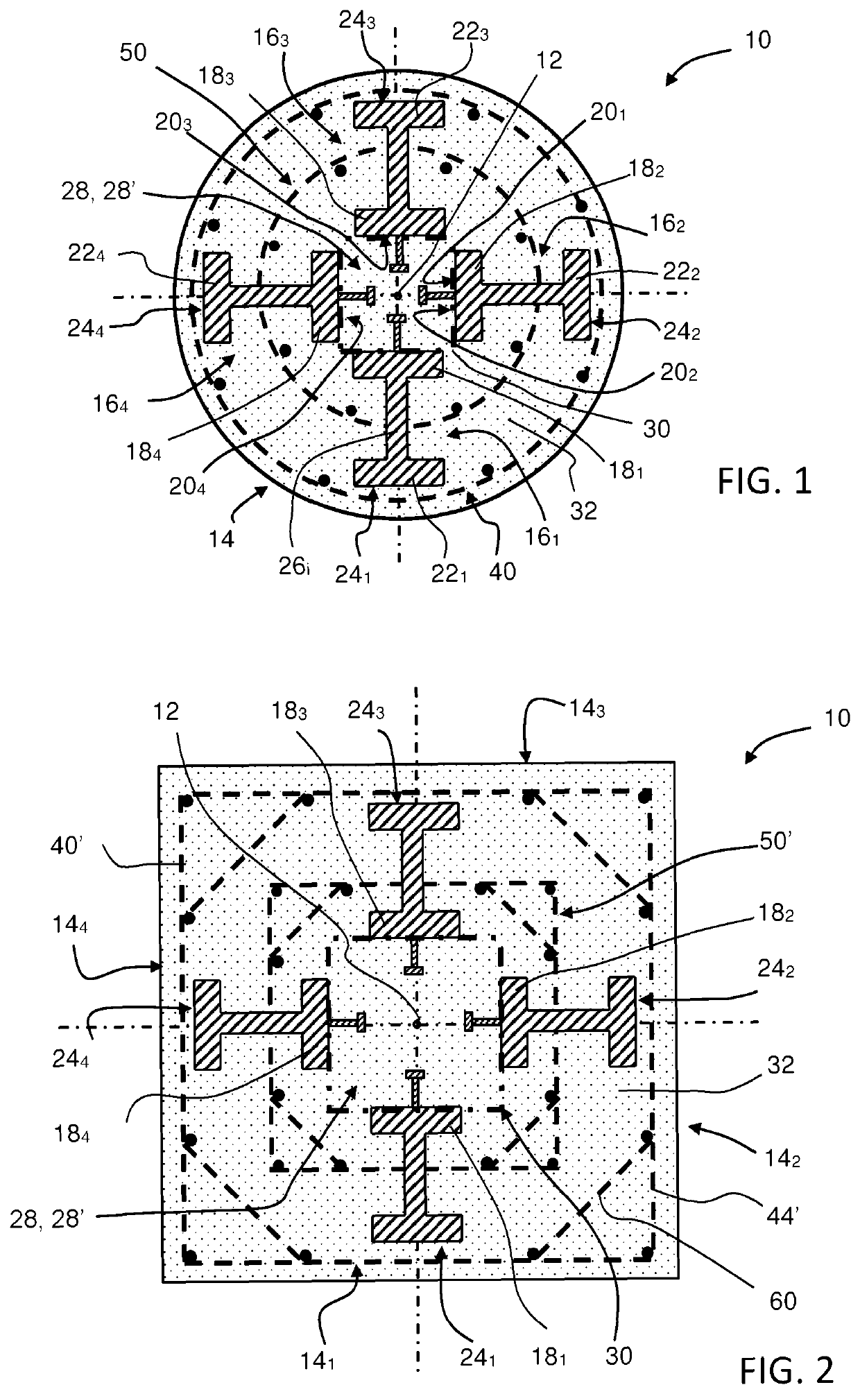
[0053]FIG. 1 schematically shows a cross-section of a first embodiment of a steel reinforced concrete column 10 in accordance with the invention (also designated in a shortened form as “the column 10”). The column 10 comprises a longitudinal central axis 12 and a shell surface (or outer envelope) 14. The longitudinal central axis 12 is perpendicular to the drawing plane. In the column of FIG. 1, the shell surface 14 is a right circular cylindrical surface having the longitudinal central axis 12 as cylinder axis. It follows that the column of FIG. 1 has a circular cross-section.

[0054]Four hot-rolled steel sections 161, 162, 163, 164 with an H-shaped section...


PUM


Abstract

A steel reinforced concrete column for a high rise building comprises a plurality of hot-rolled steel sections extending longitudinally through the concrete column. Each of these steel sections has an outward flange with an outer surface turned outwards in the concrete column, an opposite inward flange with an outer surface turned inwards in the concrete column, and a web connecting the outward flange to the inward flange. The steel sections are arranged in the concrete column so that the outer surfaces of their inward flanges at least partially delimit therein a central concrete core with n lateral sides and a transversal cross-section that forms an n-sided polygon, n being at least equal to three, and each of then lateral sides of the central concrete core being coplanar with the outer surface of the inward flange of at least one steel section.

Description

TECHNICAL FIELD[0001]The present invention generally relates to a steel reinforced concrete column for a high rise building. It further relates to a steel structure for such a steel reinforced concrete column and a high-rise building comprising such a steel reinforced concrete column.BACKGROUND ART[0002]Steel reinforced concrete columns are composite columns comprising structural steel sections encased in reinforced concrete. They are widely used in high-rise buildings and, due to their sizes, are also referred to as “mega-columns”. Taking advantage of the composite action between the concrete and the steel sections, the bearing capacity of the composite column is normally larger than the sum of the bearing capacities of the isolated concrete and steel sections.[0003]A first type of steel reinforced concrete columns has a welded steel skeleton that consists of heavy steel plates assembled on site by welding. Such a column is for example disclosed in Chinese utility model CN 20491998...

Claims


Application Information

Patent Timeline
Patent Type & Authority Applications(United States)
IPC IPC(8): E04B1/30E04C3/32E04C3/34E04C5/06
CPCE04B1/30E04C5/0622E04C3/34E04C3/32
Inventor BOGDAN, TEODORAGERARDY, JEAN-CLAUDEPOPA, NICOLETAVASSART, OLIVIERDAVIES, DONALD W.XIAO, CONGZHENCHEN, TAODENG, FEIWOOD, ANTONYTRABUCCO, DARIOLUCCHESE, ELEONORA
Owner ARCELORMITTAL INVESTIGACION Y DESARROLLO SL
Why Eureka
Try Eureka