
Devices and methods for in situ soil analysis

a technology of in situ soil and sensor device, which is applied in the field of soil analysis, can solve the problems of inability to use “in situ”, limited analysis range, and very accurate methods used in laboratory analyses, and achieve the effect of improving the quality of analysis results

Active Publication Date: 2021-07-22
STENON GMBH
View PDF2 Cites 7 Cited by
  • Summary
  • Abstract
  • Description
  • Claims
  • Application Information

AI Technical Summary

Benefits of technology

The present invention aims to improve devices and methods for in situ soil analysis. The new devices and methods make it possible to analyze additional soil properties and achieve better quality analysis results compared to existing solutions.

Problems solved by technology

Although the methods which are used in such laboratory analyses are very accurate, they cannot be used “in situ”, i.e. not without the prior taking of a sample and not on site, on the soil to be analyzed, for example on an area for agricultural or horticultural use, either because the technical equipment which is required for this purpose is not mobile, or because the analysis requires standardized environmental conditions that can only be achieved in a laboratory.
However, the available range of analyses is limited to the analysis of the water content, the pH value, the electrical conductivity and the soil type of the soil from the soil sample.
However, other parameters, such as in particular the parameters highly relevant for farmers and horticulturists concerning the content of potassium, magnesium, copper, manganese, zinc, bromine, iron, available phosphorus, humus, as well as the total nitrogen content and the total carbon content cannot be analyzed in situ at present.
In addition, on their own, none of the in situ analysis methods known to date enables the measurement results or analysis results to be documented in a manner that is reliable, from a legal point of view, as may be required in many countries as a basis for a verification of legal regulations, such as statutory fertilizer regulations etc.

Method used


Image

  • Devices and methods for in situ soil analysis
  • Devices and methods for in situ soil analysis
  • Devices and methods for in situ soil analysis

Examples


Embodiment Construction

lass="d_n">[0075]In the figures, the same reference signs are used throughout for the same or mutually corresponding elements of the invention.

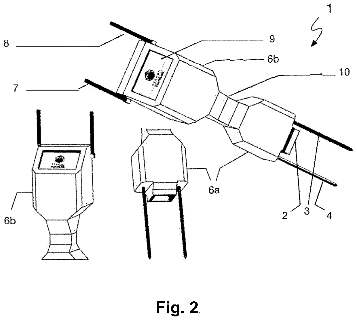
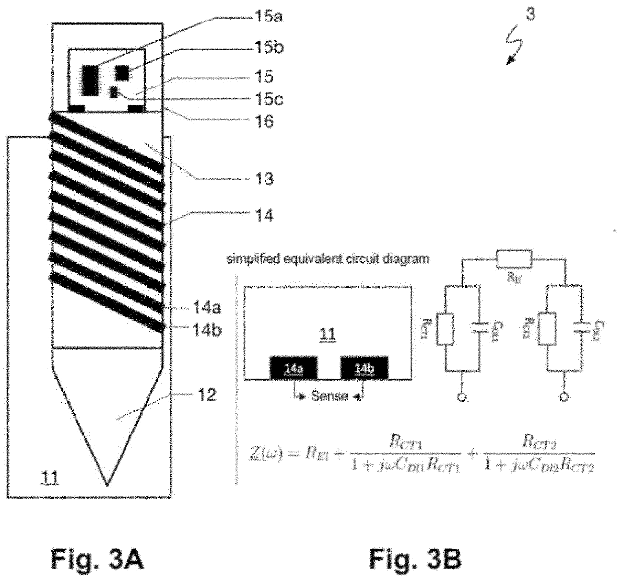
[0076]The sensor device 1 shown in FIG. 1 in accordance with an embodiment of the invention is constructed as a module, which in turn comprises several assemblies, in particular sensor assemblies, in a common housing 2. A first one of these assemblies is a combined impedance / temperature sensor assembly 3, which is at least partially constructed in a rod-like or spike-like first support element and which is configured for stabbing into soil to be analyzed. A further one of the assemblies is a potential measuring assembly 4, in particular a pH sensor assembly, which is formed by means of a second support element which, like the first support element, has a rod-like or spike-like shape and is likewise constructed for stabbing into the soil to be analyzed. Between these two assemblies 3 and 4, as well as in the immediate vicinity thereof, an abso...


PUM

PropertyMeasurementUnit
distanceaaaaaaaaaa
frequencyaaaaaaaaaa
distanceaaaaaaaaaa

Abstract

The invention relates to the field of soil analysis, in particular the technical analysis of agricultural or horticultural soils. In particular, the invention relates to a sensor device for in situ soil analysis, to a method for in situ soil analysis, and to a device set up for carrying out the soil analysis method, wherein said device, together and in interaction with one or more of said sensor devices, represents a system for in situ soil analysis. The sensor device has a sensor assembly comprising one or more sensors which are configured individually or cumulatively for the simultaneous in situ measurement of at least two of the following soil properties of a soil to be analyzed and for providing corresponding to respective measurement data: (a) impedance spectrum, (b) temperature, (c) absorption spectrum NIR-VIS-UV in a spectral range from NIR (near infrared spectral range) to UV (ultraviolet spectral range), and (d) acidic or basic character, in particular pH value. In this case, the distance between in each case two of the sensors of the sensor assembly, which is defined with respect to the respective measurement variable sensors, does not exceed a value of 10 cm.

Description

FIELD OF THE INVENTION[0001]The present invention relates to the field of soil analysis, in particular—but without this being a limitation—the technical analysis of soils used for agricultural or horticultural purposes. In particular, the invention relates to a sensor device for in situ soil analysis, a method for in situ soil analysis and a device which is arranged to carry out the soil analysis method, whereby this device, together and in co-operation with one or more of to said sensor devices constitutes a system for in situ soil analysis.BACKGROUND OF THE INVENTION[0002]In the field of soil analysis, laboratory-based methods of analysis are currently mainly used, which are based on the taking one or more samples from a soil to be analyzed, transporting them to a suitable laboratory where they are processed and analyzed. Thereafter, a corresponding analysis report is prepared and sent to a recipient or client. As a rule, the time between the taking of the sample and the notificat...

Claims


Application Information

Patent Timeline
Patent Type & Authority Applications(United States)
IPC IPC(8): G01N33/24G01N21/31G01N27/04
CPCG01N33/24G01N2033/245G01N27/043G01N21/31G01N27/223G01N27/4035G01N21/3563G01N33/245
Inventor GRABBERT, NIELSROTH, DOMINIC
Owner STENON GMBH
Learn More