Ignition device for internal combustion engine
a technology of internal combustion engine and ignition device, which is applied in the direction of machines/engines, electrical control, mechanical equipment, etc., can solve the problems of shortening the charging period, generating noise over-exposed on the primary voltage, and not accurately measuring the primary voltag
- Summary
- Abstract
- Description
- Claims
- Application Information
AI Technical Summary
Benefits of technology
Problems solved by technology
Method used
Image
Examples
first embodiment
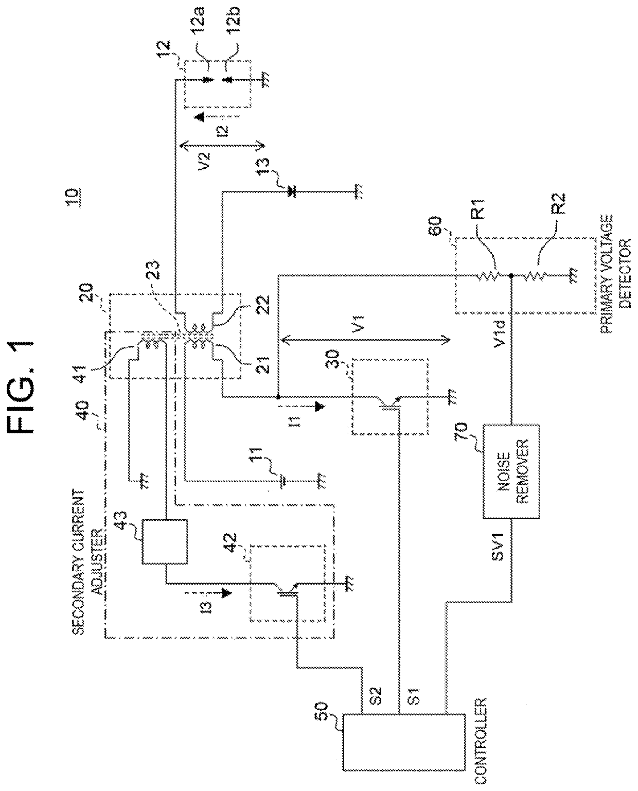
[0023]FIG. 1 is a configuration diagram for illustrating an ignition device for an internal combustion engine according to a first embodiment. As illustrated in FIG. 1, an ignition device 10 for an internal combustion engine includes an ignition coil 20, a first switch 30, a secondary current adjuster 40, a controller 50, a primary voltage detector 60, and a noise remover 70.
[0024]The ignition coil 20 includes a primary coil 21, a secondary coil 22, and a core 23. The primary coil 21 is wound around the core 23.
[0025]The primary coil 21 has a high-voltage side terminal connected to a positive terminal of a DC power supply 11. The DC power supply 11 has a negative terminal connected to the ground. As the DC power supply 11, a lead-acid battery is used, for example. The DC power supply 11 is configured to output a rated power supply voltage of 12 V. The primary coil 21 is supplied with electric power from the DC power supply 11.
[0026]The primary coil 21 has a low-voltage side terminal...
second embodiment
[0113]Next, an ignition device for an internal combustion engine according to a second embodiment is described.
[0114]FIG. 4 is a configuration diagram for illustrating the ignition device for an internal combustion engine according to the second embodiment. The same components as the components illustrated in FIG. 1 are denoted by the same reference symbols, and a detailed description thereof is omitted.
[0115]As illustrated in FIG. 4, the adjusting coil 41 has one end connected to the positive terminal of the DC power supply 11, and another end connected to the second switch 42. The configuration is similar to that in the first embodiment except that the one end of the adjusting coil 41 is connected to the positive terminal of the DC power supply 11.
[0116]A direction of a magnetic flux generated in the core 23 by an electric current flowing through the adjusting coil 41 is the same as a direction of a magnetic flux generated in the core 23 by an electric current flowing through the ...
third embodiment
[0122]Next, an ignition device for an internal combustion engine according to a third embodiment is described.
[0123]FIG. 5 is a configuration diagram for illustrating the ignition device for an internal combustion engine according to the third embodiment. The sane components as the components illustrated in FIG. 1 are denoted by the same reference symbols, and a detailed description thereof is omitted.
[0124]As illustrated in FIG. 5, the secondary current adjuster 40 of an ignition device 10 for an internal combustion engine according to the third embodiment includes a third switch 44 and a second current limiter 45.
[0125]The third switch 44 is an IGBT. The third switch 44 is connected, via the second current limiter 45, to one end of the primary coil 21 that is opposite to the side of the primary coil 21 to which the DC power supply 11 is connected. In other words, the secondary current adjuster 40 is connected to the primary coil 21 in parallel to the first switch 30 between the pr...
PUM
 Abstract
Description
Claims
Application Information
 - R&D
- Intellectual Property
- Life Sciences
- Materials
- Tech Scout
- Unparalleled Data Quality
- Higher Quality Content
- 60% Fewer Hallucinations
Browse by: Latest US Patents, China's latest patents, Technical Efficacy Thesaurus, Application Domain, Technology Topic, Popular Technical Reports.
© 2025 PatSnap. All rights reserved.Legal|Privacy policy|Modern Slavery Act Transparency Statement|Sitemap|About US| Contact US: help@patsnap.com


