
Ignition device for internal combustion engine

a technology for internal combustion engines and ignition devices, which is applied in the direction of electric control, machines/engines, mechanical equipment, etc., can solve the problems of buried primary voltage in primary interruption noise, short charging period, and inability to detect primary voltage in the charging period

Active Publication Date: 2021-08-31
MITSUBISHI ELECTRIC CORP
View PDF13 Cites 0 Cited by
  • Summary
  • Abstract
  • Description
  • Claims
  • Application Information

AI Technical Summary

Benefits of technology

[0009]The present disclosure has been made to solve the above-mentioned problem, and therefore has an object to provide an ignition device for an internal combustion engine that can suppress difficulty in measuring a primary voltage of an ignition coil.

Problems solved by technology

Meanwhile, the noise superimposed on the primary voltage is generated mainly due to leakage inductance of the primary coil irrespective of the current value of the secondary current.
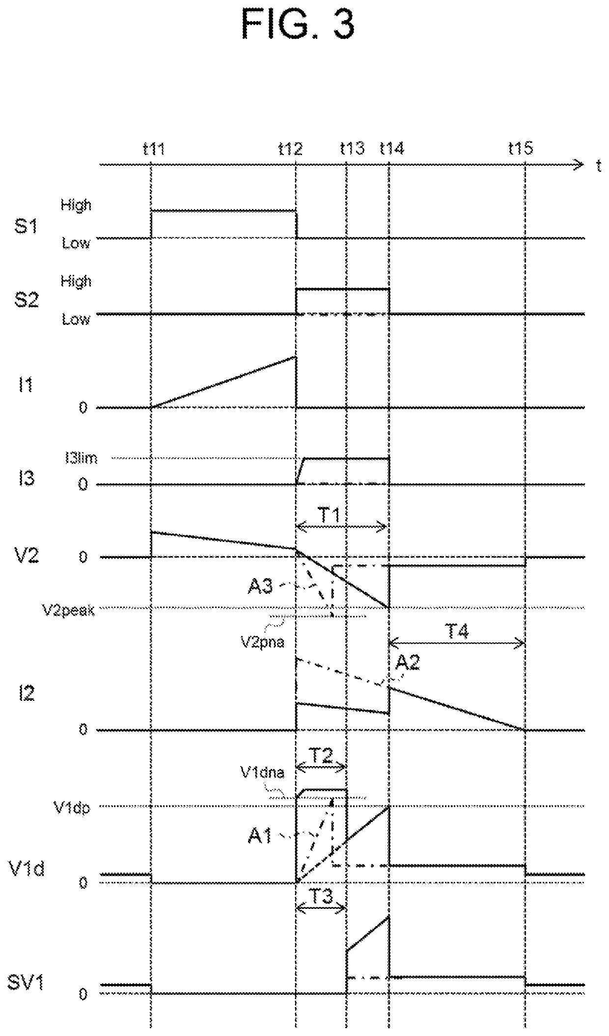
Therefore, the charging period may become shorter than the primary interruption noise generation period in some cases.
As described above, in the ignition device for an internal combustion engine in which the secondary current is increased to such an extent that the charging period becomes shorter than the primary interruption noise generation period, a signal of the primary voltage in the charging period may be buried in primary interruption noise to be undetectable in some cases.
Therefore, in this case, it becomes difficult to measure a secondary voltage in the charging period and the dielectric breakdown voltage indirectly.

Method used


Image

  • Ignition device for internal combustion engine
  • Ignition device for internal combustion engine
  • Ignition device for internal combustion engine

Examples


first embodiment

[0024]

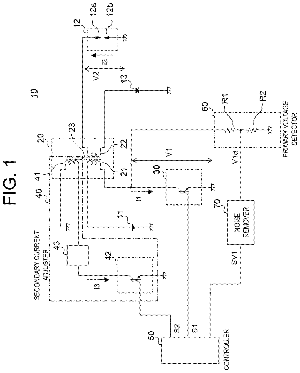
[0025]FIG. 1 is a configuration diagram for illustrating an ignition device for an internal combustion engine according to a first embodiment. As illustrated in FIG. 1, an ignition device 10 for an internal combustion engine includes an ignition coil 20, a first switch 30, a secondary current adjuster 40, a controller 50, a primary voltage detector 60, and a noise remover 70.

[0026]The ignition coil 20 includes a primary coil 21, a secondary coil 22, and a core 23. The primary coil 21 is wound around the core 23.

[0027]The primary coil 21 has a high-voltage side terminal connected to a positive terminal of a DC power supply 11. The DC power supply 11 has a negative terminal connected to the ground. As the DC power supply 11, a lead-acid battery is used, for example. The DC power supply 11 is configured to output a rated power supply voltage of 12 V. The primary coil 21 is supplied with electric power from the DC power supply 11.

[0028]The primary coil 21 has a low-voltage side te...

second embodiment

[0115

[0116]Next, an ignition device for an internal combustion engine according to a second embodiment is described.

[0117]FIG. 4 is a configuration diagram for illustrating the ignition device for an internal combustion engine according to the second embodiment. The same components as the components illustrated in FIG. 1 are denoted by the same reference symbols, and a detailed description thereof is omitted.

[0118]As illustrated in FIG. 4, the adjusting coil 41 has one end connected to the positive terminal of the DC power supply 11, and another end connected to the second switch 42. The configuration is similar to that in the first embodiment, except that the one end of the adjusting coil 41 is connected to the positive terminal of the DC power supply 11.

[0119]A direction of a magnetic flux generated in the core 23 by an electric current flowing through the adjusting coil. 41 is the same as a direction of a magnetic flux generated in the core 23 by an electric current flowing throu...

third embodiment

[0125

[0126]Next, an ignition device for an internal combustion engine according to a third embodiment is described.

[0127]FIG. 5 is a configuration diagram for illustrating the ignition device for an internal combustion engine according to the third embodiment. The same components as the components illustrated in FIG. 1 are denoted by the same reference symbols, and a detailed description thereof is omitted.

[0128]As illustrated in FIG. 5, the secondary current adjuster 40 of an ignition device 10 for an internal combustion engine according to the third embodiment includes a third switch 44 and a second current limiter 45.

[0129]The third switch 44 is an IGBT. The third switch 44 is connected, via the second current limiter 45, to one end of the primary coil 21 that is opposite to the side of the primary coil 21 to which the DC power supply 11 is connected. In other words, the secondary current adjuster 40 is connected to the primary coil 21 in parallel to the first switch 30 between t...


PUM


Abstract

An ignition device for an internal combustion engine includes an ignition coil, a first switch, a secondary current adjuster, and controller The ignition coil includes a primary coil, a core, and a secondary coil. The first switch switches an energized state of the primary coil between an ON state and an OFF state. The secondary current adjuster adjusts a current value of a secondary current flowing through the secondary coil. The controller controls the secondary current adjuster so that a current value of the secondary current in at least a part of a charging period of the ignition plug, which is a period from when the energized state of the primary coil is switched from the ON state to the OFF state by the first switch to when dielectric breakdown occurs in the ignition plug, becomes smaller than a peak value of the secondary current after the dielectric breakdown occurs.

Description

BACKGROUND OF THE INVENTION[0001]1. Field of the Invention[0002]The present disclosure relates to an ignition device for an internal combustion engine.[0003]2. Description of the Related Art[0004]Hitherto, there is known an ignition device for an internal combustion engine, which is configured to detect an abnormality in dielectric breakdown voltage of an ignition plug, a misfire in the internal combustion engine, or other incidents. The dielectric breakdown voltage is a secondary voltage generated on a secondary coil side of an ignition coil at a moment when dielectric breakdown occurs between electrodes of the ignition plug. For example, in an internal combustion engine control apparatus of the related art, a primary voltage generated on a primary coil side of the ignition coil is measured, and a dielectric breakdown voltage is measured indirectly based on a period in which the measured primary voltage exceeds a reference voltage (see Japanese Patent Application Laid-open No. 2016...

Claims


Application Information

Patent Timeline
Patent Type & Authority Patents(United States)
IPC IPC(8): F02P3/05F02P3/09F02P17/12F02P15/10F02D41/20F02P3/055
CPCF02P17/12F02P3/051F02P3/053F02P3/09F02P15/10F02D2041/2058F02P3/055F02P2017/121F02P2017/125F02P9/007
Inventor NAKAMURA, TOSHIFUMIINADA, TAKAHIKO
Owner MITSUBISHI ELECTRIC CORP
Learn More