
Accessible Tub and Shower

a technology for showers and tubs, applied in the direction of wing accessories, door/window fittings, construction fastening devices, etc., can solve the problems of ineffective use, inconvenient opening of doors, and inability to enter and exi

Inactive Publication Date: 2021-07-22
CLARKE DONALD H
View PDF14 Cites 1 Cited by
  • Summary
  • Abstract
  • Description
  • Claims
  • Application Information

AI Technical Summary

Benefits of technology

This invention is a walk-in bathtub that has a swinging door for easy access. The door is held closed during use by an electromagnetic door latch that can be activated or deactivated by a rapid-release touch switch. The switch can be used to deactivate the latch in an emergency to allow the door to swing open and drain quickly. The tub is constructed with solid surface materials, which make it strong, durable, and leak-proof. The invention also includes an optional floor drain or emergency catch basin and can initiate an audible, visible, or electronically transittable notification alert when the quick-release touch switch is used. The invention provides a clean and finished look with no visible door latch hardware. It can be fitted with conventional faucets, shower heads, and associated piping.

Problems solved by technology

Because tubs with relatively high sidewalls can make it difficult to enter and exit the tub safely, a hinged door is often provided in the front wall of the tub to permit a user to step into or out of the tub over a low sill located beneath the door.
A disadvantage and safety hazard associated with such tubs is that the door is not easily opened until enough water is drained out of the tub to lower the water level inside the tub to the level of the sill beneath the door.
The use of tubs with doors that can be opened to enter or exit the tub has been found to reduce the likelihood that a user will slip and fall while entering or exiting the tub but is not effective for use in an emergency situation where a user is unable to drain the water from a filled tub, open the door inwardly, and then exit according to normal use.
Recent experiences have demonstrated that the use of walk-in tubs having inwardly swinging doors can pose a serious risk and be dangerous for the user under some circumstances.
Also, as a greater portion of the user's body collapses into the foot well, the displaced water causes the water level inside the tub to rise higher, applying even greater pressure against the door.

Method used


Image

  • Accessible Tub and Shower
  • Accessible Tub and Shower
  • Accessible Tub and Shower

Examples


Embodiment Construction

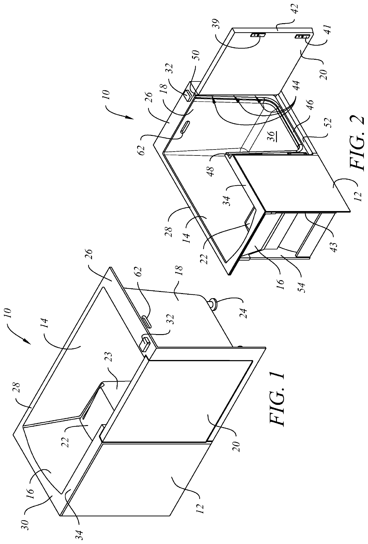
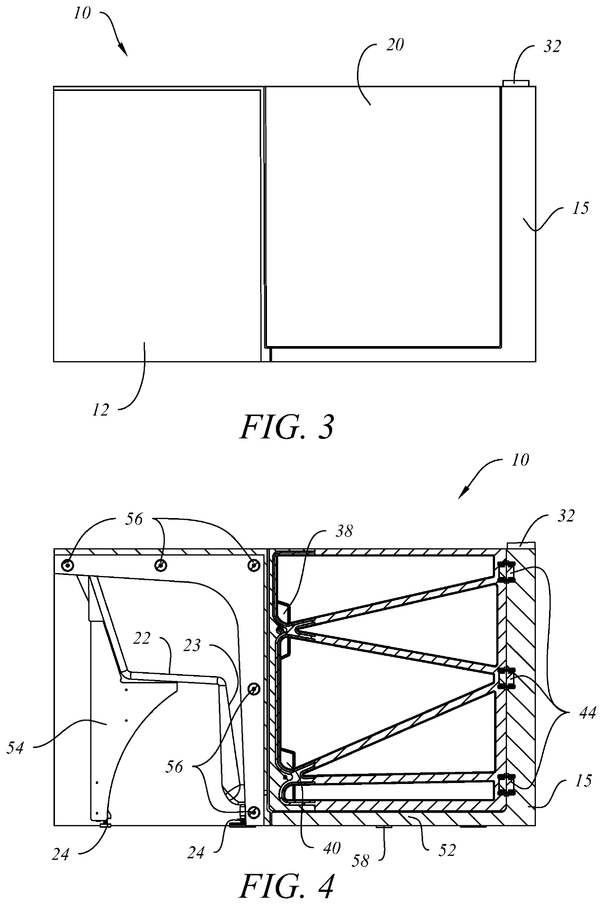
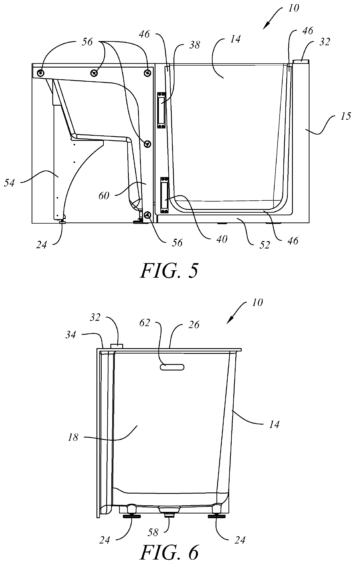
[0019]Referring to an embodiment of the invention as depicted in FIGS. 1-3, walk-in tub 10 desirably comprises a unitary body with a front tub wall (not visible) covered by detachable front wall panel 12, a back wall 14, opposed end walls 16, 18, bottom wall 36, a top flange further comprising sections 26, 28, 30 and 34 that are contiguous with the front, back and end walls, and a hinged, outwardly swinging door 20. The tub body is desirably supported by threaded adjustable legs 24 (visible in FIGS. 1 and 4-6). Seat surface 22 is desirably contiguous with the front wall (behind detachable front wall panel 12, back 14 and left end wall 16, and is also supported by seat support wall 23 that is contiguous with the front, back and bottom walls. In one satisfactory embodiment of the invention, the principal inside and bottom walls, seat, seat support wall and top flange of walk-in tub 10 are unitarily formed by casting the solid surface material using a variety of molds, and then joining...


PUM


Abstract

A walk-in tub, or combination walk-in tub and shower, having a front wall with an outwardly swinging door permitting easy entry into and egress from the tub by a user and an electromagnetic door latch assembly further comprising a plurality of electromagnetic door latches that are operatively interconnected to an electrical controller, a power supply and a rapid-release touch switch that can be selectively manipulated to interrupt the power supply to the electromagnetic latches, thereby allowing the door to swing open under emergency conditions even when the tub is filled with water.

Description

1. FIELD OF THE INVENTION[0001]This invention relates to a modern tub or tub and shower combination that is easily accessible, embodies improved safety features, and is constructed using solid surface materials that are strong, durable, stain resistant and leak-proof.2. DESCRIPTION OF RELATED ART[0002]In the past, bathtubs and hydrotherapy tubs have been provided, for example in hospitals, physical therapy centers and athletic training facilities, and are used for physical therapy or relaxation under the supervision of trained attendants. More recently, jetted bathtubs and hydrotherapy tubs have become more widely available for residential use by the general public as well as for elderly or physically impaired physically individuals. Such tubs typically have higher sidewalls than a conventional bathtub and accommodate a higher water fill level. Such tubs sometimes have a seat built into the tub that is disposed above the interior bottom surface of the tub and a foot-well located in ...

Claims


Application Information

Patent Timeline
Patent Type & Authority Applications(United States)
IPC IPC(8): A47K3/00E05B47/00E05B41/00E05B65/00
CPCA47K3/006E05B47/0046E05Y2900/114E05B65/00E05Y2201/462E05B41/00E05C19/166E05B17/0025
Inventor CLARKE, DONALD H.
Owner CLARKE DONALD H
Learn More