Spray pump

Pending Publication Date: 2021-06-17
SAMHWAP&T
View PDF1 Cites 0 Cited by
  • Summary
  • Abstract
  • Description
  • Claims
  • Application Information

AI Technical Summary

Benefits of technology

The present invention is a spray pump that can spray the contents in a uniform manner. Additionally, it is designed to minimize the flow path exposed to outside air, which helps prevent the contents from getting evaporated or contaminated.

Problems solved by technology

As a result, it may occur that the pumped liquid content is unable to easily pass through the orifice having a small diameter, and this in turn can result in an inability to eject a content in a uniform manner.
Also, in the conventional spray pump, the length of the flow path exposed to outside air is long.
This can incur problems of the content evaporating, spoiling, or being polluted by impurities.

Method used


Image

  • Spray pump
  • Spray pump
  • Spray pump

Examples


Embodiment Construction

[0024]Below, a detailed description is provided of certain embodiments of the present invention, with reference to the appended drawings. In the descriptions referencing the appended drawings, the same reference numerals are assigned to the same or corresponding elements, regardless of the figure number, and redundant descriptions are omitted.

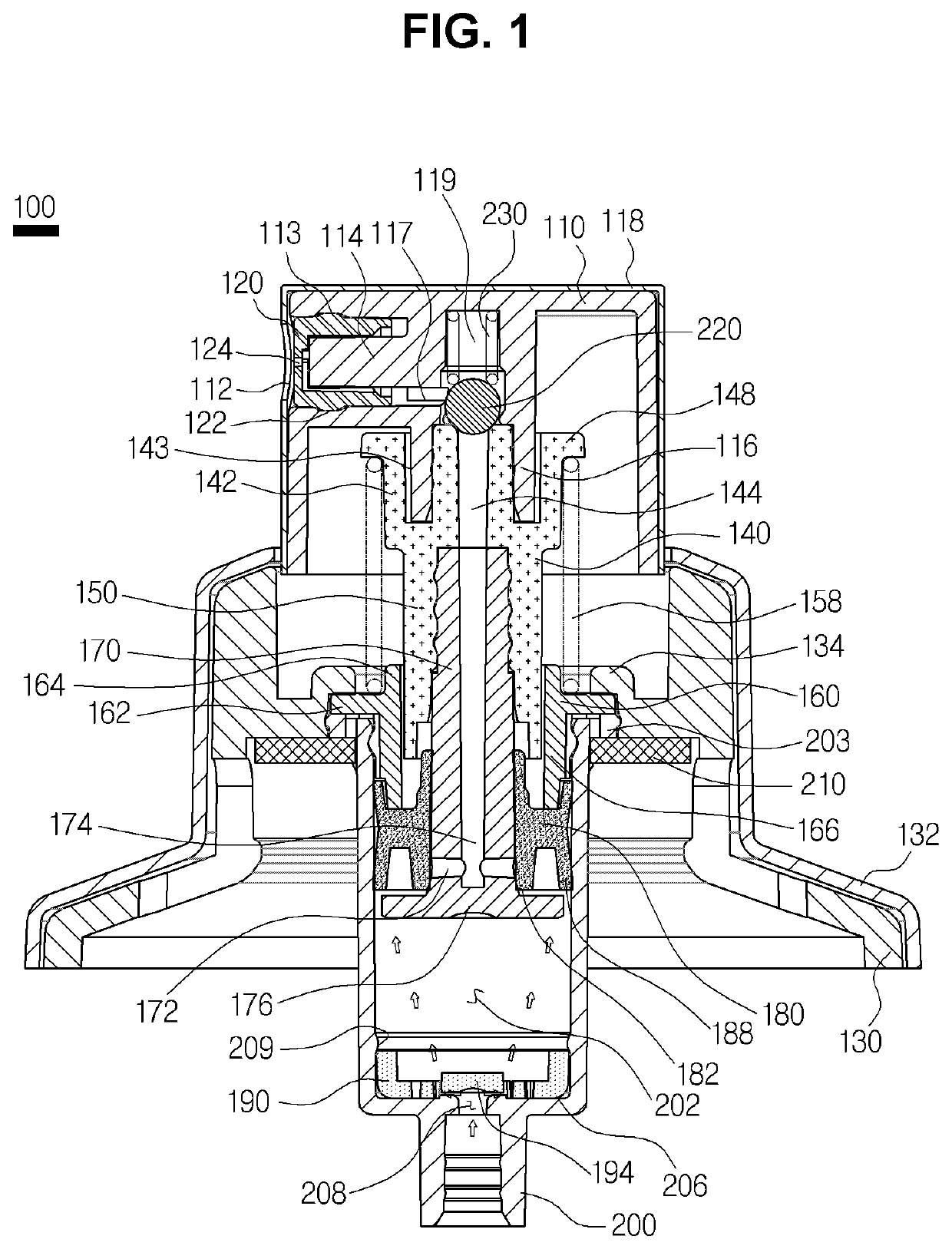
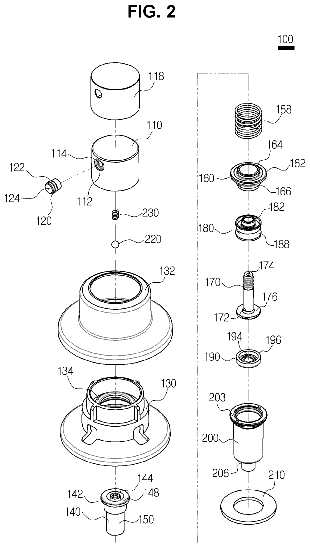
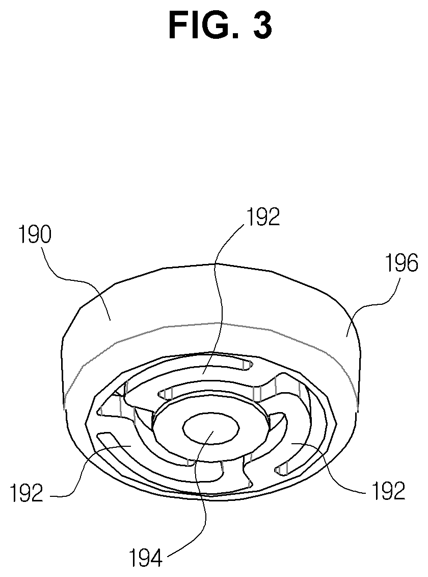
[0025]FIG. 1 is a cross-sectional view illustrating a spray pump 100 according to an embodiment of the present invention, and FIG. 2 is an exploded perspective view of the spray pump 100 illustrated in FIG. 1. FIG. 3 is a perspective view illustrating the disk 190 in a spray pump 100 according to an embodiment of the present invention. FIG. 4 is a cross-sectional view illustrating the spray pump in FIG. 1 when the nozzle 110 is moved downward, and FIG. 5 is a magnified view of part A in FIG. 4.

[0026]Incidentally, FIG. 1 illustrates the spray pump 100 when there is no external force applied, so that the nozzle 110 is raised as much as possible. ...


PUM


Abstract

A spray pump is disclosed. A spray pump according to one aspect of the present invention comprises: a housing having an inlet space and coupled to a container inlet; a housing cover coupled to an upper end of the housing; a disk for opening or closing the housing according to a pressure of the inlet space; a valve movably inserted inside the housing cover and having a valve head, a valve passage formed in the valve head, and a valve body; a guide having a portion inserted into the valve body and another portion located outside the valve body, and including a guide passage corresponding to a flow passage through which content is discharged; a pump spring for providing an elastic force for urging the valve upward; a piston movably inserted into an outer circumferential surface of the guide, and opening or closing the guide passage by means of an upward and downward movement of the valve; a nozzle having a coupling protrusion coupled to the valve head and in communication with the valve passage; a valve ball positioned inside the nozzle and capable of closing the upper end of the valve passage; and a pump spring for urging the valve ball downward.

Description

BACKGROUNDTechnical Field[0001]The present invention relates to a spray pump capable of spraying a content evenly.Description of the Related Art[0002]In a cosmetic container and the like, a spray pump may be coupled to the opening at the upper part of a container holding a liquid content such as a perfume, etc., to eject and spray the content to the exterior in designated amounts. When the user presses down on a nozzle corresponding to a button so as to spray the liquid content, the content that had entered the inside of the spray pump may be pressurized, move upward along the discharge passage, and be sprayed through the nozzle. When the pressure on the nozzle is released, the discharge passage may be mechanically closed by the rising of the nozzle, the pressure inside the pump may be lowered, and the content may be drawn in from the container to make up for the pressure loss.[0003]A spray pump such as the above is being used not only for spraying perfumes and cosmetics but also a ...

Claims


Application Information

Patent Timeline
IPC IPC(8): B05B11/00
CPCB05B11/3001B05B11/3074B05B11/3067B05B11/3052B05B11/3047B05B11/0064B05B11/1023B05B11/1069B05B11/1047B05B11/1074B05B11/1001B05B11/1052B05B11/1067
Inventor LEE, KYUNGCHANGLEE, JOONHONG
Owner SAMHWAP&T
Why Eureka
Try Eureka