
Micro component structure and micro component display device

a micro-component and display device technology, applied in the field of micro-component structure, can solve the problems of weak structural strength of the fixing structure and the width of the fixing structure, and achieve the effect of good structural strength

Active Publication Date: 2021-06-03
PLAYNITRIDE DISPLAY CO LTD
View PDF0 Cites 1 Cited by
  • Summary
  • Abstract
  • Description
  • Claims
  • Application Information

AI Technical Summary

Benefits of technology

This invention is about a way to make a strong micro component structure. It uses a two-layer fixing system that includes a first layer that supports the micro component and a second layer that is placed on top of the first layer. This design increases the structural strength of the overall structure. The refractive index of the first layer is higher than the refractive index of the second layer, which improves the brightness of the overall structure after it is transferred.

Problems solved by technology

Because the fixing structure is made of a photosensitive material or a single-layer dielectric film at present, the width of the fixing structure is limited due to the reduction in the size of the micro light emitting diode, and the structural strength of the fixing structure is weak.
Therefore, how to enable the fixing structure to temporarily hold the micro light emitting diode and more easily and efficiently transport and transfer the micro light emitting diode between the carrier substrate and the receiving substrate has become one of the issues that attract attention in the industry at present.

Method used


Image

  • Micro component structure and micro component display device
  • Micro component structure and micro component display device
  • Micro component structure and micro component display device

Examples


Embodiment Construction

[0035]Embodiments of the invention describe a structure of a micro component (such as a Micro Light Emitting Diode (Micro LED) or a micro chip), so as to be taken and transferred onto a receiving substrate. The receiving substrate may be a display substrate, a light emitting substrate, substrates having functional components such as transistors or Integrated Circuits (ICs), or other substrates having lines, but is not limited thereto. Although some embodiments of the invention specifically describe Micro LEDs including p-n diodes, it should be understood that the embodiments of the invention are not limited thereto. Some embodiments may also be applied to other micro components, and by virtue of the mode, the components are designed to control the execution of preset electronic functions (such as diodes, transistors and ICs) or photon functions (LEDs and lasers).

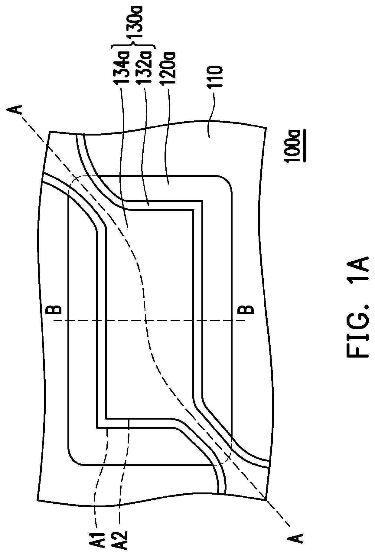
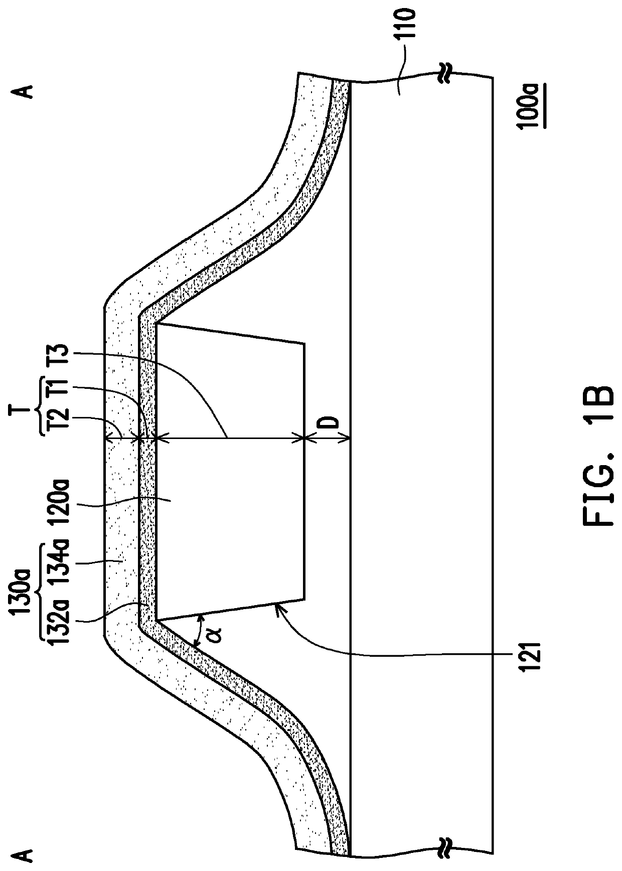
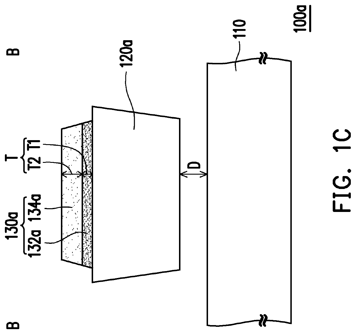
[0036]FIG. 1A is a schematic top diagram of a micro component structure according to an embodiment of the invention. FIG. ...


PUM


Abstract

A micro component structure includes a substrate, a micro component and a fixing structure. The micro component and the fixing structure are disposed on the substrate. The micro component has a spacing from the substrate. The fixing structure includes a first supporting layer and a second supporting layer. The micro component is connected to the substrate through the fixing structure. The first supporting layer is connected to the micro component and located between the second supporting layer and the micro component. A refractive index of the first supporting layer is greater than a refractive index of the second supporting layer.

Description

CROSS-REFERENCE TO RELATED APPLICATION[0001]This application claims the priority benefit of Taiwan application serial no. 108144006, filed on Dec. 3, 2019. The entirety of the above-mentioned patent application is hereby incorporated by reference herein and made a part of this specification.BACKGROUND OF THE INVENTIONField of the Invention[0002]The disclosure relates to a semiconductor structure, and in particular relates to a micro component structure.Description of Related Art[0003]At present, the transfer of a micro light emitting diode is mainly performed through electrostatic force or magnetic force to transfer the micro light emitting diode on a carrier substrate onto a receiving substrate. In general, the micro light emitting diode is held by a fixing structure to enable the micro light emitting diode to be easily taken from the carrier substrate and transported and transferred onto the receiving substrate, and the fixing structure is configured to fix the micro light emittin...

Claims


Application Information

Patent Timeline
IPC IPC(8): H01L33/58H01L33/24H01L25/075
CPCH01L33/58H01L25/0753H01L33/24H01L33/56H01L33/54
Inventor LO, YU-YUNWU, BO-WEILIANG, SHENG-CHIEHYANG, SHIANG-NING
Owner PLAYNITRIDE DISPLAY CO LTD
Learn More