Automatic artifact detection and pulse sequence modification in magnetic resonance imaging

a technology of magnetic resonance imaging and artifact detection, applied in the field of magnetic resonance imaging, can solve problems such as geometric distortion, anomalies within magnetic resonance images, artifacts or anomalies etc., and achieve the highest likelihood score of image improvement, improve the quality of a series of magnetic resonance images, and improve the effect of magnetic resonance images

Active Publication Date: 2021-05-27
KONINKLJIJKE PHILIPS NV
View PDF0 Cites 2 Cited by
  • Summary
  • Abstract
  • Description
  • Claims
  • Application Information

AI Technical Summary

Benefits of technology

[0005]Embodiments of the invention provide for a means of reducing artifacts in magnetic resonance images by using a MRI artifact detection module that comprises at least one neural network. The MRI artifact detection module identifies artifacts in a magnetic resonance image and provides a list of suggested pulse sequence command changes. That is, the magnetic resonance image with its metal data is input the MRI artifact detection module. The MRI artifact detection module in configured in software to recognise and identify image artifacts in the magnetic resonance image. The MRI artifact detection module's trained neural network functions as an artifact classifier outputting an artifact classification of the input. magnetic resonance image the list of suggested pulse sequence command changes. One of the list of suggested pulse sequence command changes may be used to modify the pulse sequence commands. The modified pulse sequence commands can for example be used to reacquire the magnetic resonance image. When a series of magnetic resonance images are being acquired, the modified pulse sequence commands can also be used to correct and improve the quality of subsequently acquired magnetic resonance image.
[0030]In another embodiment the selection criteria is received from a selection module that is configured to select the chosen pulse sequence commands using a predetermined criteria applied to the image improvement likelihood score. That is, e.g. the selection of the chosen pulse sequence command change is made on the basis of the image improvement likelihood score of the pulse sequence command change. In other words, the pulse sequence command may be changed to a changed pulse sequence command that has a higher, or even the highest image improvement likelihood score. Thus, the changed pulse sequence is highly likely to lead to reduction of the artifact level of the magnetic resonance image. This embodiment may be beneficial because it may provide for an automated improvement of magnetic resonance images. In another embodiment execution of the machine-executable instructions further cause the processor to display a warning prompt on the user interface. The warning prompt may be displayed if at least one image improvement likelihood score is above a predetermined threshold. The warning prompt displays a list of the suggested pulse sequence command changes. The selection of the chosen pulse sequence command changes is received from the user interface. This embodiment may be beneficial because it may provide for a means for an operator to manually improve the magnetic resonance images.

Problems solved by technology

However, the acquisition of a magnetic resonance imaging data is not instantaneous and voluntary and / or involuntary subject motion can cause artifacts or anomalies with the magnetic resonance image.
Additionally, incorrectly configuring the magnetic resonance imaging system or the presence of metallic implants with the subject can also cause anomalies within the magnetic resonance image.
Among the most common problems are motion artifacts caused by bulk subject movement, cardiac motion, or blood flow, aliasing artifacts due to improper scan planning, signal voids due to magnetic materials in the patient, geometric distortion caused by field inhomogeneity, and chemical shift artifacts

Method used


Image

  • Automatic artifact detection and pulse sequence modification in magnetic resonance imaging
  • Automatic artifact detection and pulse sequence modification in magnetic resonance imaging
  • Automatic artifact detection and pulse sequence modification in magnetic resonance imaging

Examples


Embodiment Construction

[0061]Like numbered elements in these figures are either equivalent elements or perform the same function. Elements which have been discussed previously will not necessarily be discussed in later figures if the function is equivalent.

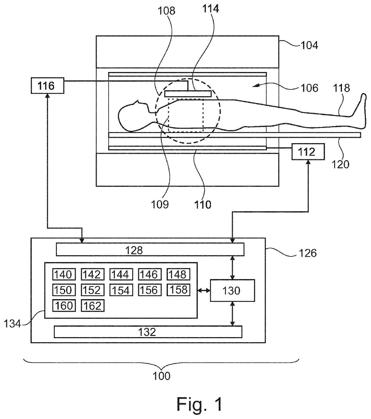
[0062]FIG. 1 shows an example of a magnetic resonance imaging system 100 with a magnet 104. The magnet 104 is a superconducting cylindrical type magnet with a bore 106 through it. The use of different types of magnets is also possible; for instance it is also possible to use both a split cylindrical magnet and a so called open magnet. A split cylindrical magnet is similar to a standard cylindrical magnet, except that the cryostat has been split into two sections to allow access to the iso-plane of the magnet, such magnets may for instance be used in conjunction with charged particle beam therapy. An open magnet has two magnet sections, one above the other with a space in-between that is large enough to receive a subject: the arrangement of the two secti...


PUM


Abstract

The invention provides for a magnetic resonance imaging system (100, 300). The execution of machine executable instructions causes a processor (130) controlling the magnetic resonance imaging system to control (200) the magnetic resonance imaging system to acquire the magnetic resonance imaging data (144) using pulse sequence commands (142) and reconstruct (202) a magnetic resonance image (148). Execution of the machine executable instructions causes the processor to receive (204) a list of suggested pulse sequence command changes (152) by inputting the magnetic resonance image and image metadata (150) into an MRI artifact detection module (146, 146′, 146″). The MRI artifact detection module comprises at least one neural network, which has been trained using images from failed magnetic resonance imaging protocols and / or magnetic resonance data extracted from the magnetic resonance imaging protocols labeled as failed accessed from a log file (312) which logs the execution of previous magnetic resonance imaging protocols. Execution of the machine executable instructions further causes the processor to receive (206) a selection of a chosen pulse sequence command change (158) from the list of suggested pulse sequence command changes. Execution of the machine executable instructions further causes the processor to modify (208) the pulse sequence commands using the chosen pulse sequence command change.

Description

FIELD OF THE INVENTION[0001]The invention relates to magnetic resonance imaging, in particular to reduction of artifacts during magnetic resonance imaging.BACKGROUND OF THE INVENTION[0002]A large static magnetic field is used by Magnetic Resonance Imaging (MRI) scanners to align the nuclear spins of atoms as part of the procedure for producing images within the body of a subject. This large static magnetic field is referred to as the BO field or the main magnetic field. Various quantities or properties of the subject can be measured spatially using MRI. However, the acquisition of a magnetic resonance imaging data is not instantaneous and voluntary and / or involuntary subject motion can cause artifacts or anomalies with the magnetic resonance image. Additionally, incorrectly configuring the magnetic resonance imaging system or the presence of metallic implants with the subject can also cause anomalies within the magnetic resonance image. Among the most common problems are motion arti...

Claims


Application Information

Patent Timeline
Patent Type & Authority Applications(United States)
IPC IPC(8): G01R33/54G01R33/56G01R33/565A61B5/055
CPCG01R33/543G01R33/5608A61B5/7207A61B5/055G01R33/565
Inventor SOMMER, KARSTENSAALBACH, AXELHELLE, MICHAEL GUNTERWEISS, STEFFENSCHULKE, CHRISTOPHE MICHAEL JEAN
Owner KONINKLJIJKE PHILIPS NV
Why Eureka
Try Eureka