
Multistage pump

a multi-stage pump and pump body technology, applied in the direction of machines/engines, mechanical equipment, liquid fuel engines, etc., can solve the problems of reducing the efficiency of the pump, so as to reduce the hydraulic loss, the effect of reducing the hydraulic loss and small cross-section

Pending Publication Date: 2021-05-27
SULZER MANAGEMENT AG
View PDF6 Cites 0 Cited by
  • Summary
  • Abstract
  • Description
  • Claims
  • Application Information

AI Technical Summary

Benefits of technology

The present invention provides an improved crossover or crossunder pipe for multistage pumps that overcomes the problems of conventional passageways such as difficulty in cleaning and high hydraulic losses. The new design has a smaller cross section, increased accuracy of inner surfaces, and reduced roughness of the internal surfaces that lead to reduced hydraulic losses. Additionally, the new design allows for flexibility in positioning of the volute end and dump end, which further optimizes the hydraulic design.

Problems solved by technology

It has been discovered that in the conventional multistage pumps, the length of the passageways combined with the small cross-sectional areas (low specific speeds in particular) provide difficulties at the foundries.
The requirements for this cleaning process adds cost and time to the casting process.
Moreover, if the passageways are not cleaned effectively, a partially obstructed passageway or poor surface quality, could have detrimental effects on the pump performance.
For example, in the conventional passageways long crossover / crossunder channels must be close to the body of the casing for formation and mass optimization, which translates into highly curved passageways with associated hydraulic losses.

Method used


Image

  • Multistage pump
  • Multistage pump
  • Multistage pump

Examples


Embodiment Construction

[0048]Selected embodiments will now be explained with reference to the drawings. It will be apparent to those skilled in the art from this disclosure that the following descriptions of the embodiments are provided for illustration only and not for the purpose of limiting the invention as defined by the appended claims and their equivalents.

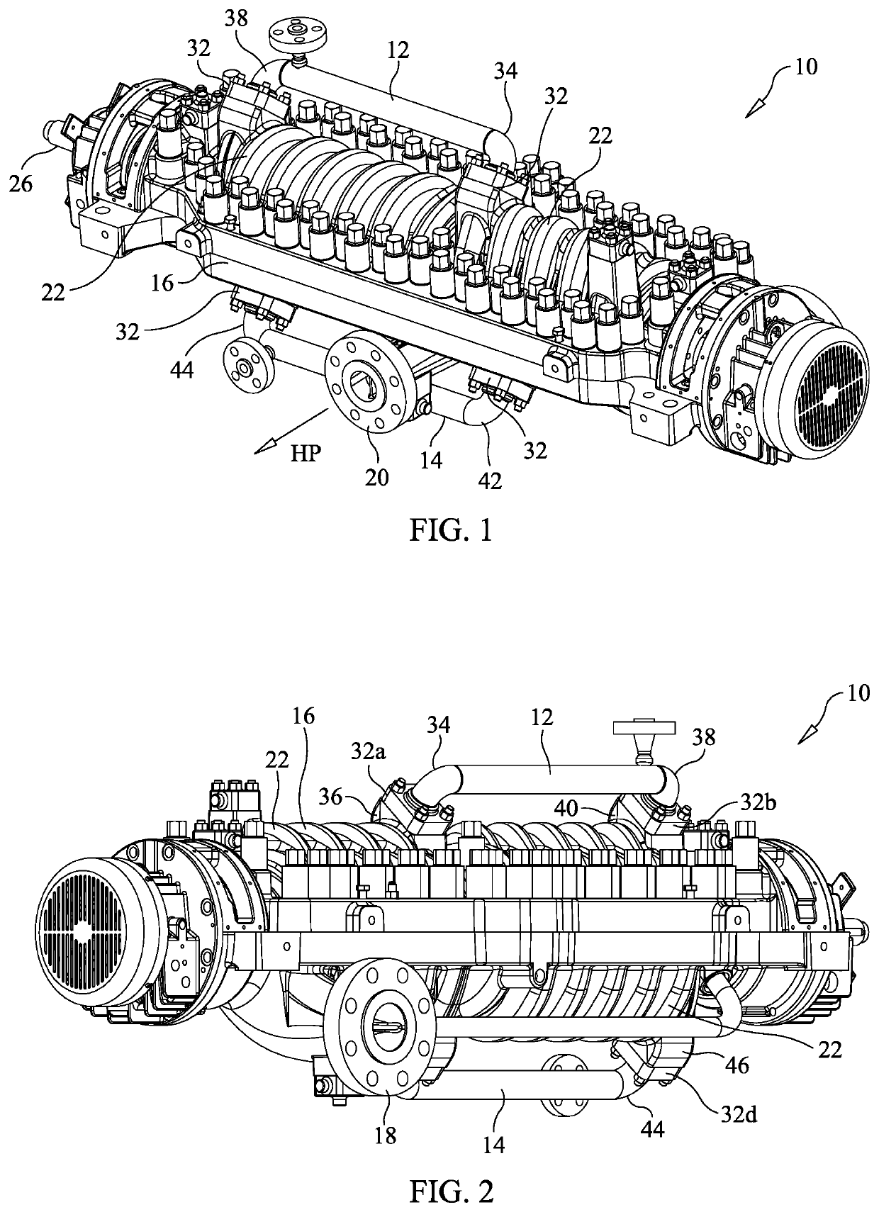
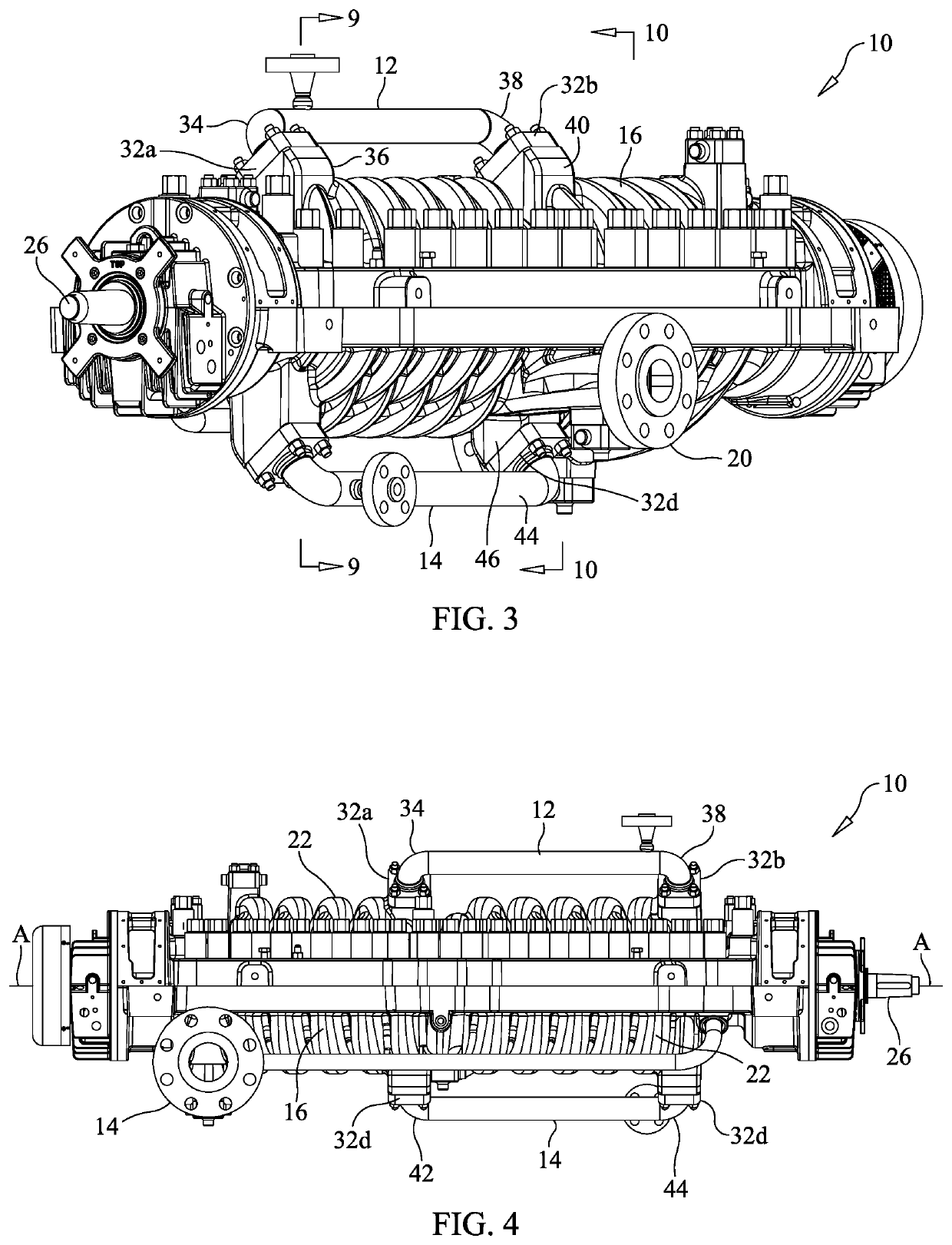
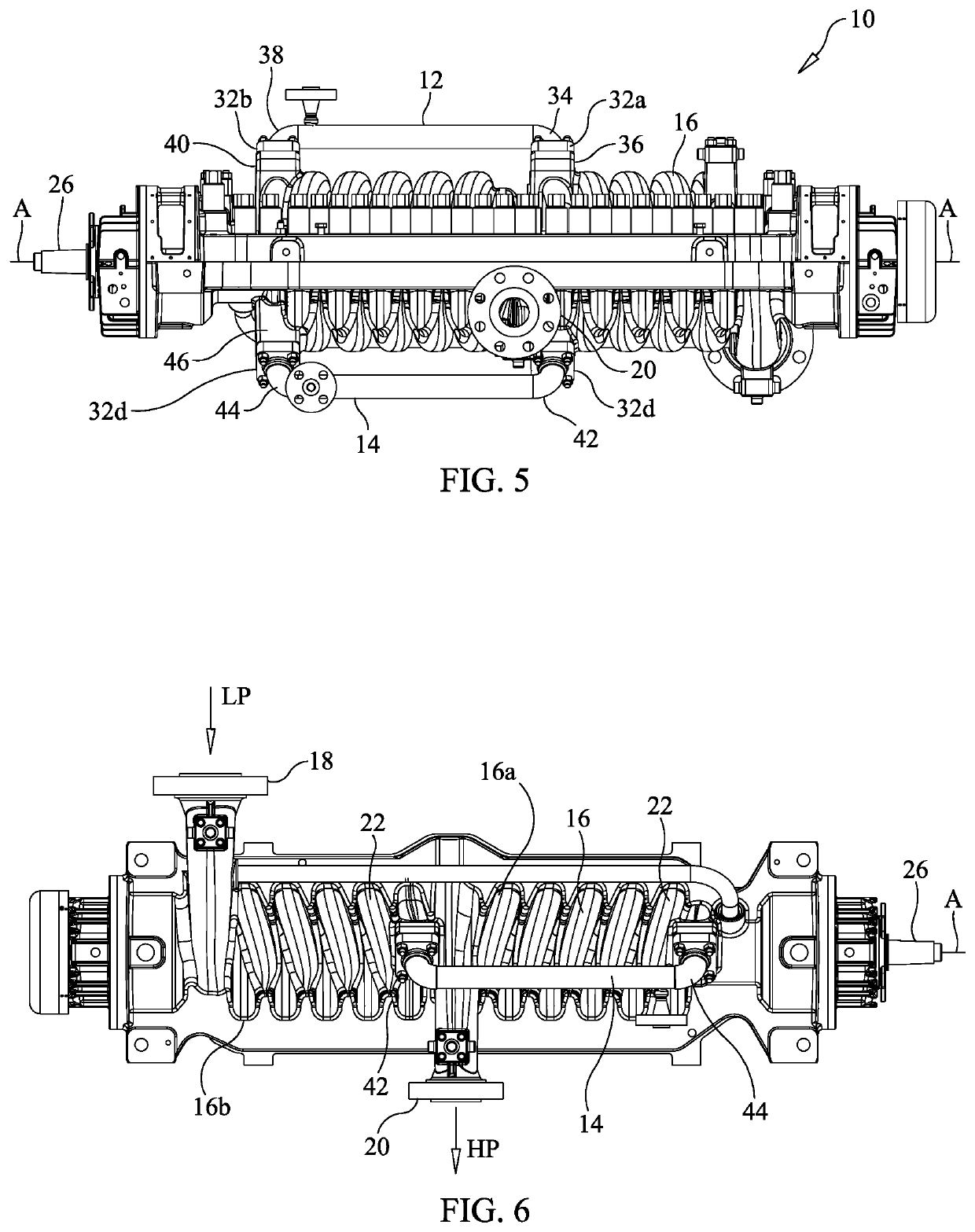
[0049]Referring initially to FIG. 1, a multistage pump 10 that includes a cross over pipe 12 and a crossunder pipe 14 is illustrated in accordance with a first embodiment. In particular, the multistage pump 10 includes a cylindrical pump casing (or housing) 16, an impeller shaft, a first impeller 28, a second impeller 30, the crossover pipe 12 and the crossunder pipe 14.

[0050]The casing 16 includes a pump inlet 18 through which the multistage process fluid enters the pump at the low pressure side LP as indicated by the arrow, and a pump outlet 20 for discharging the process fluid with an increased pressure at the high pressure HP side as indicated...


PUM


Abstract

A multistage pump includes a pump casing, a shaft, a first impeller, a second impeller, and a pipe. The shaft is rotatably disposed within the pump casing and has a longitudinal axis. The first impeller is disposed within the casing at a first position along the shaft. The second impeller is disposed within the casing at a second position and along the shaft. The pipe is detachably attached to the pump casing, and has an inlet and an outlet, the inlet disposed at the discharge of the first impeller and the outlet disposed at an eye of the second impeller, such that discharge from the first impeller can be conveyed to the eye of the second impeller.

Description

CROSS-REFERENCE TO RELATED APPLICATION[0001]This application claims benefit of U.S. Provisional Application No. 62 / 941,370, filed Nov. 27, 2019, the contents of which are hereby incorporated herein by reference.BACKGROUNDField of the Invention[0002]This invention generally relates to a multistage pump. In particular, the invention relates to a pipe for a multistage pump.Background Information[0003]Conventional multistage pumps or multistage double volute pumps generally include opposed impeller designs. The opposed impellers are disposed facing opposite directions in order to balance the axial thrust generated by the rotating element. Crossover passageways convey product from the discharge of the mid-stage impeller to the far side of the pump, and into the eye of the subsequent opposing stage impeller. In the conventional multistage pumps the crossover passageways are integrally formed with the with the pump casing, and are rectangular or trapezoidal in cross-section.SUMMARY[0004]It...

Claims


Application Information

Patent Timeline
Patent Type & Authority Applications(United States)
IPC IPC(8): F04D29/42F04D1/06F15D1/04
CPCF04D29/42F04D1/06F05B2260/60F05B2240/14F15D1/04F04D29/2222F04D29/426F04D29/669F04D29/628F04D29/445F04D29/4293
Inventor MILOJEVIC, STEVE
Owner SULZER MANAGEMENT AG
Learn More