
Rotatable form shadow casting device

a shadow casting and rotating technology, applied in the direction of planar light sources, lighting and heating equipment with built-in power, etc., can solve the problems of not being able to finally get to sleep, many people struggling with their ability to fall asleep, and racing thoughts, so as to prevent repetition, effective shadow display, and high contrast

Active Publication Date: 2021-05-13
MORE MICHAEL +1
View PDF0 Cites 0 Cited by
  • Summary
  • Abstract
  • Description
  • Claims
  • Application Information

AI Technical Summary

Benefits of technology

The present invention is a device for creating decorative shadows on surfaces. The device is made of durable material that can withstand wear and tear. It has a rotating form that can be attached or designed in different shapes and patterns, allowing for different decorative shadows. The device has a motor for rotating the form, which is protected from external forces. It creates a relaxing image without the need for additional night lighting. The technical effects of this invention are its durability, flexibility, and ability to create decorative shadows without the need for a separate lighting fixture.

Problems solved by technology

Many persons struggle with their ability to fall asleep.
Numerous issues can cause a person to be able to finally get to sleep, and one of the most prevalent issues is racing thoughts.
When a person is thinking too much or focusing mentally on a number of different issues, their capability to rest is severely degraded.
This can lead to crying spells and refusal to be laid down to rest in a crib.
Further, a small child or infant may be afraid of the dark, and not being able to see anything frightens them such that the affected child cries until their parent can come back and comfort them.
Unfortunately, the capability of sight then may cause the child to be fascinated or curious about something they can see, and the issues of racing thoughts as described above can manifest.
However, over time a child may bore of the repetitive nature of the mobile, and the aforementioned night light is a requirement so that a child can see the mobile itself should the room be darkened.

Method used


Image

  • Rotatable form shadow casting device
  • Rotatable form shadow casting device
  • Rotatable form shadow casting device

Examples


Embodiment Construction

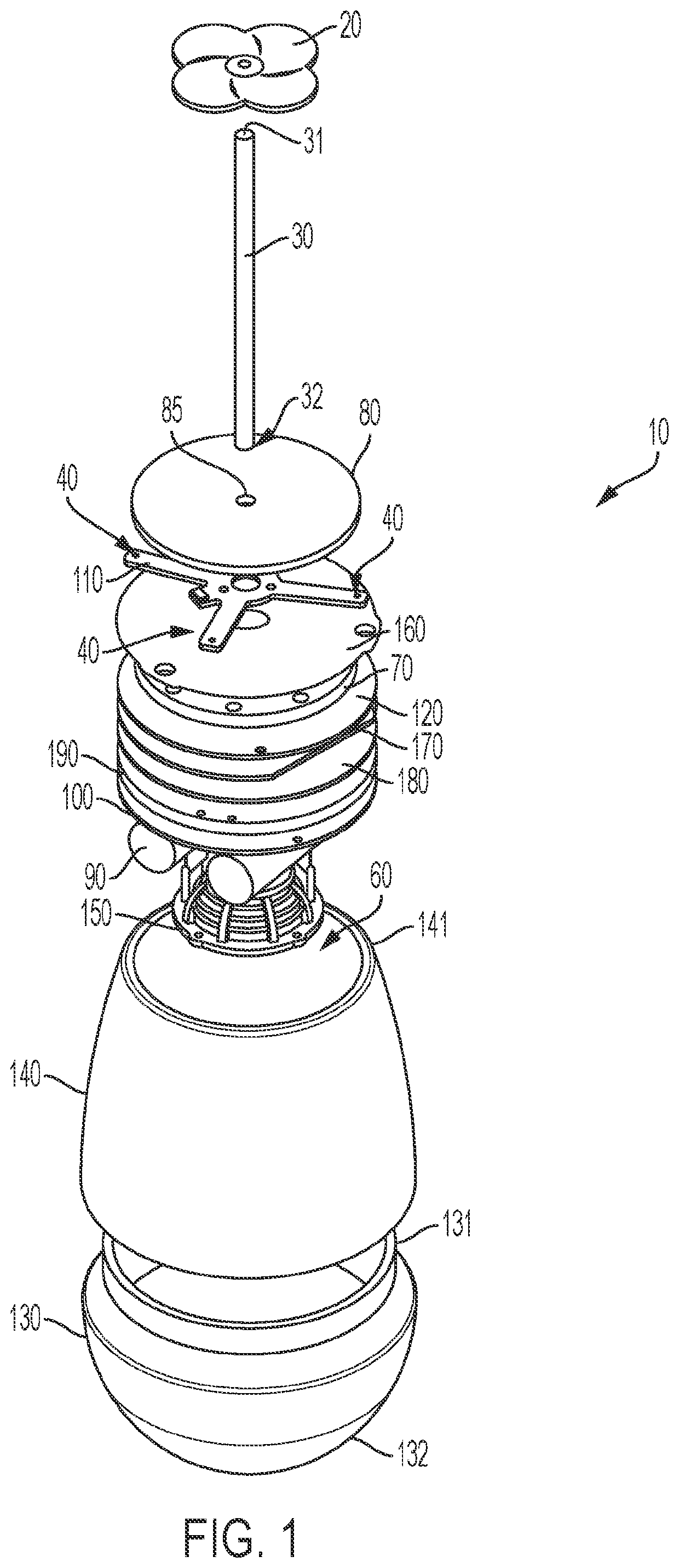
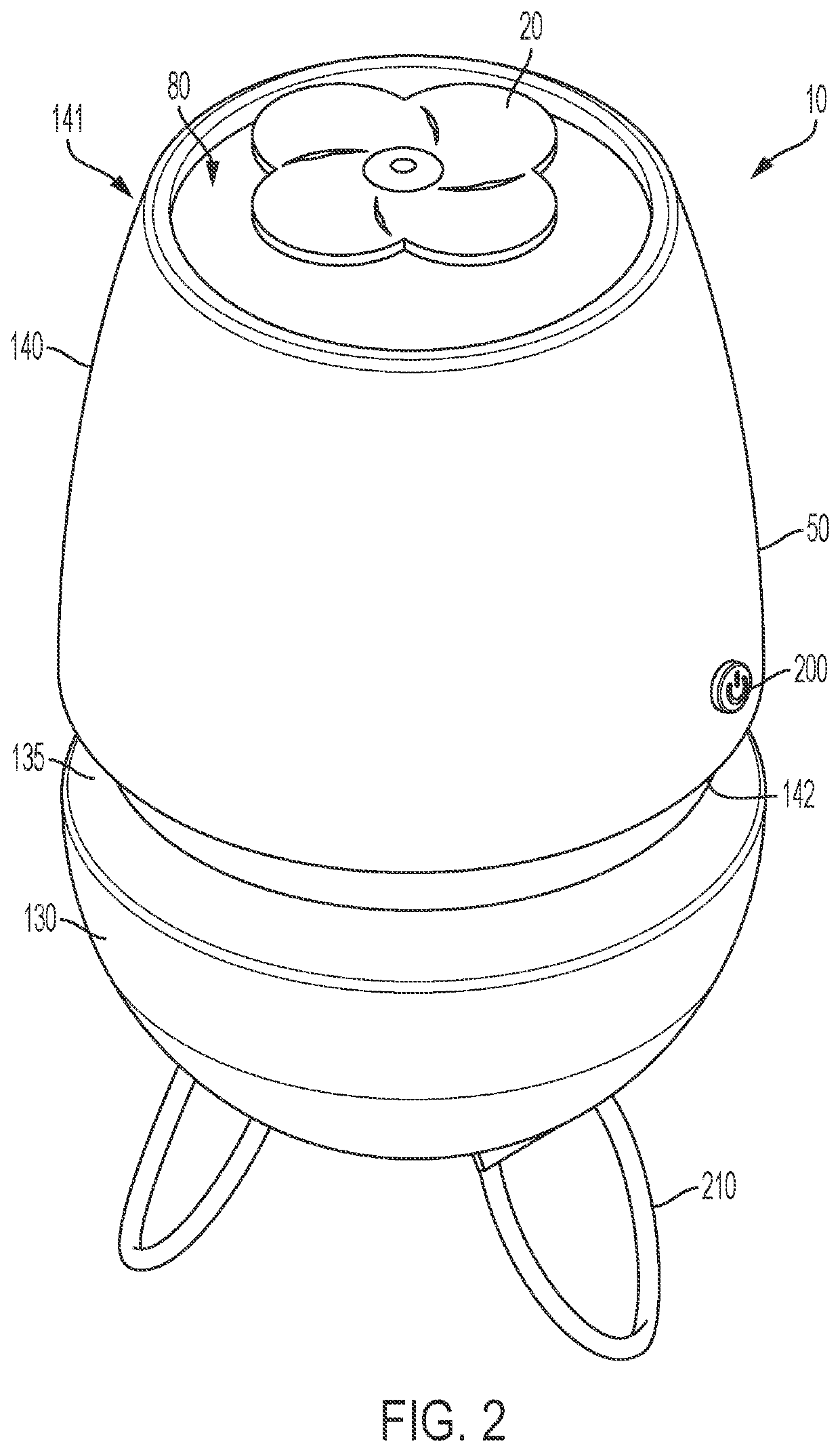
[0033]Referring now to the drawings in detail, FIG. 1 illustrates a preferred embodiment of a rotatable form shadow casting device 10 constructed in accordance with the present invention. This embodiment is an exploded view and is shown with a lower housing unit 130 having a bottom end 132 and a top end 131. The upper housing unit 140 couples to the lower housing unit 130. The components that are contained within the housing cavity 60 are displayed outside and above the upper housing unit top end 141 and said housing cavity 60, though when assembled they reside therein.

[0034]A speaker 150 is depicted, which may transmit audio signals. Contained within or near the speaker 150 may be an audio driver or said audio driver may be on the processor 130, as depicted in FIG. 4. The speaker 150 may additionally be a two-way speaker containing a microphone therein, or the microphone may be a separate component in another location within the housing cavity 60. As earlier-discussed, the processo...


PUM


Abstract

A light emitting device with a rotating form thereon, said device having a motor and a power source contained within a generally durable housing having a lens and an elongated spire extending outside of the durable housing and through an opening contained within the lens, said elongated spire additionally having a decorative rotatable form positioned on a distal end of the elongated spire, and at least one light source directing emitted light at the rotatable form, such that crisp hard shadows are produced on outlying surfaces. A power source is provided, connected to a motor and processor so as to move or rotate the spire and thus the form, causing the lights to cast moving decorative shadows on an exterior surface.

Description

CROSS REFERENCE TO RELATED APPLICATION[0001]This application claims the benefit of U.S. Provisional Application 62 / 932,384, filed Nov. 7, 2019.FIELD[0002]The present disclosure is directed to the field of generalized illumination devices, and more particularly to a new and useful device for creating casting shadows which are illuminated on a flat surface.BACKGROUND[0003]Many persons struggle with their ability to fall asleep. Numerous issues can cause a person to be able to finally get to sleep, and one of the most prevalent issues is racing thoughts. When a person is thinking too much or focusing mentally on a number of different issues, their capability to rest is severely degraded.[0004]Babies make up one group of persons that struggle with racing thoughts. It is thought that babies are so mentally stimulated by many different things that they sometimes cannot get to sleep quickly, to the detriment of their parents. Most parents prefer their child to be on a sleep schedule so tha...

Claims


Application Information

Patent Timeline
Patent Type & Authority Applications(United States)
IPC IPC(8): F21V14/08A61M21/02
CPCF21V14/08A61M2021/0044A61M21/02F21S10/00F21W2121/00A61M2021/0027A61M2205/103A61M2205/8206A61M2205/3592A61M2205/3569A61M2205/505A61M2205/3375G03B21/001F21S9/00F21Y2105/00F21V23/0435F21V33/0056Y10S362/806
Inventor MORE, MICHAELKNECHTEL, JOHN
Owner MORE MICHAEL
Learn More