Monitoring system to identify unregistered persons entering premises and to secure rooms containing registered occupants

a technology of monitoring system and registered occupants, applied in the direction of computer control, process and machine control, instruments, etc., can solve the problems of not being able to require each person, unable to automatically identify persons, and difficult to provide adequate security in an open premises

Active Publication Date: 2021-05-13
SMARTER BUILDING TECH ALLIANCE INC
View PDF1 Cites 1 Cited by
  • Summary
  • Abstract
  • Description
  • Claims
  • Application Information

AI Technical Summary

Benefits of technology

[0009]In another embodiment, a system for detecting an unknown person and performing a lockdown procedure comprises a plurality of modules, each of the plurality of modules comprising an occupancy sensor and a wireless transceiver; a wireless gateway for communicating with one or more of the plurality of modules; and a server coupled to the wireless gateway, wherein the server is configured to instruct a wireless transceiver in a first module to locate a computing device within a wireless footprint of the first module when the occupancy sensor in the first module detects a person within an occupancy footprint of the first module and to implement a lockdown procedure when no computing device is located, the lockdown procedure comprising automatically closing and locking a door in proximity to the person.

Problems solved by technology

It is increasingly difficult to provide adequate security in an open premises, where there are numerous points of entry to the premises and it is not feasible to require each person to be frisked by a security guard or to walk through a metal detector when they enter the premises.
One drawback in the prior art is that there is no way to automatically identify persons 110a, 110b, 110c, 110d, and 110e except through visual inspection by another person.
As a result, it is extremely difficult to ascertain whether each person who is located within premises 100 is someone who has a legitimate reason for being on premises 100 (e.g., the person is a teacher) or whether the person has visited premises 100 for a malicious reason (e.g., the person will soon become an active shooter).

Method used


Image

  • Monitoring system to identify unregistered persons entering premises and to secure rooms containing registered occupants
  • Monitoring system to identify unregistered persons entering premises and to secure rooms containing registered occupants
  • Monitoring system to identify unregistered persons entering premises and to secure rooms containing registered occupants

Examples


Embodiment Construction

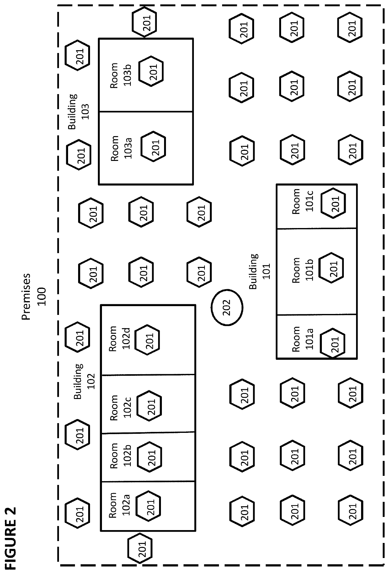
[0036]FIG. 2 depicts one embodiment of the invention. A plurality of modules 201 are installed throughout premises 100. For example, modules 201 can be installed as fixtures throughout premises 100. Gateway 202 optionally is placed within premises 100 as well.

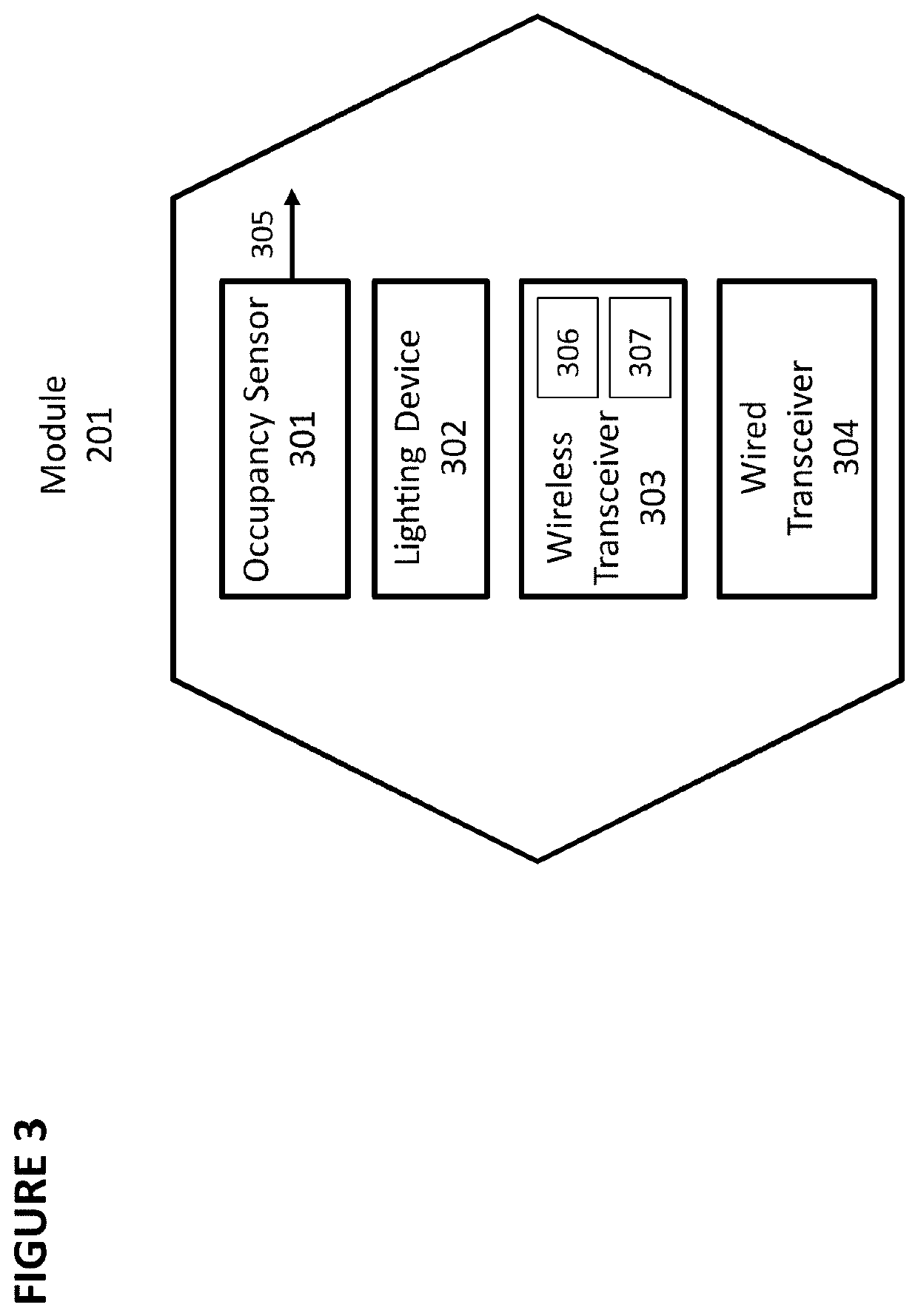
[0037]FIG. 3 depicts module 201 in greater detail. Module 201 comprises occupancy sensor 301, lighting device 302, wireless transceiver 303, and optionally, wired transceiver 304.

[0038]Occupancy sensor 301 is a motion detecting device that can detect the presence of a person within occupancy radius 401 (shown in FIG. 4, where occupancy footprint 400 is the area in which occupancy is detected) using infrared, ultrasonic, microwave, or other technology. Occupancy sensor 301 generates output 305. In one configuration, output 305 is a single-bit digital output, where output 305 is a ‘0’ when no motion is detected and is a ‘1’ when motion is detected, or vice-versa.

[0039]Lighting device 302 is a device that emits light, such as an i...


PUM


Abstract

The disclosed embodiments provide an improved monitoring and security system to identify the presence of persons within a premises, to track the relative location of the person as he or she traverse the premises, and to generate an alert and optionally enter a lockdown mode if the person does not possess a pre-registered computing device or wireless transceiver. In the lockdown mode, doors optionally can be shut and locked through remote or local control or automatically if the distance between the person and the particular door falls below a predetermined threshold.

Description

FIELD OF THE DISCLOSURE[0001]The disclosed embodiments provide an improved monitoring and security system to identify the presence of persons within a premises, to track the relative location of the person as he or she traverse the premises, and to generate an alert and optionally enter a lockdown mode if the person does not possess a pre-registered computing device or wireless transceiver.BACKGROUND[0002]It is increasingly difficult to provide adequate security in an open premises, where there are numerous points of entry to the premises and it is not feasible to require each person to be frisked by a security guard or to walk through a metal detector when they enter the premises. This is typically true for most schools, office complexes, community fairs, shopping malls, and other facilities. This problem has been shown to be particularly acute in light of the recent mass shootings at schools.[0003]FIG. 1 depicts exemplary premises 100. Buildings 101, 102, and 103 are located on pr...

Claims


Application Information

Patent Timeline
Patent Type & Authority Applications(United States)
IPC IPC(8): E05F15/72G08B15/00G08B21/02G08B25/10E05B47/00E05F15/77G05B15/02G07C9/00
CPCE05F15/72G08B15/004G08B21/02G08B25/10E05Y2900/132E05F15/77G05B15/02G07C9/00111E05B47/00G08B15/007E05F15/73E05Y2800/426E05Y2201/41G08B25/002G08B13/00G07C9/28
Inventor BUCHANAN, BENJAMINGARCIA, TONYACERNESE, SHANEHANLON, RICHLOESER, CHRISMARTIN, KEVIN
Owner SMARTER BUILDING TECH ALLIANCE INC
Why Eureka
Try Eureka